Image capturing system and control method of the same

a technology of image capturing and control method, which is applied in the field of image capturing system, can solve the problems of inability to perform fine operations related to image operations by the operator, inability to transmit/receive signals other than image data related signals, and inability to perform still image capturing using high pixel ccd, etc., and achieves easy synchronization and high image quality.

Inactive Publication Date: 2005-08-18
CANON KK
View PDF5 Cites 36 Cited by
  • Summary
  • Abstract
  • Description
  • Claims
  • Application Information

AI Technical Summary

Benefits of technology

[0012] The present invention has been made in light of solving the aforementioned problems, and provides an image capturing system which allows a user to perform still photography with high image quality, zoom and focus image operations, automa

Problems solved by technology

It is impossible to perform fine operations related to image operations by the operator.
However, with conventional systems, it is impossible to transmit/receive signals other than image data related signals (e.g., 12-bit digital image data, VD signal, HD signal, and image data sampling signal).
Accordingly, it is also imp

Method used


Image

  • Image capturing system and control method of the same
  • Image capturing system and control method of the same
  • Image capturing system and control method of the same

Examples


first embodiment

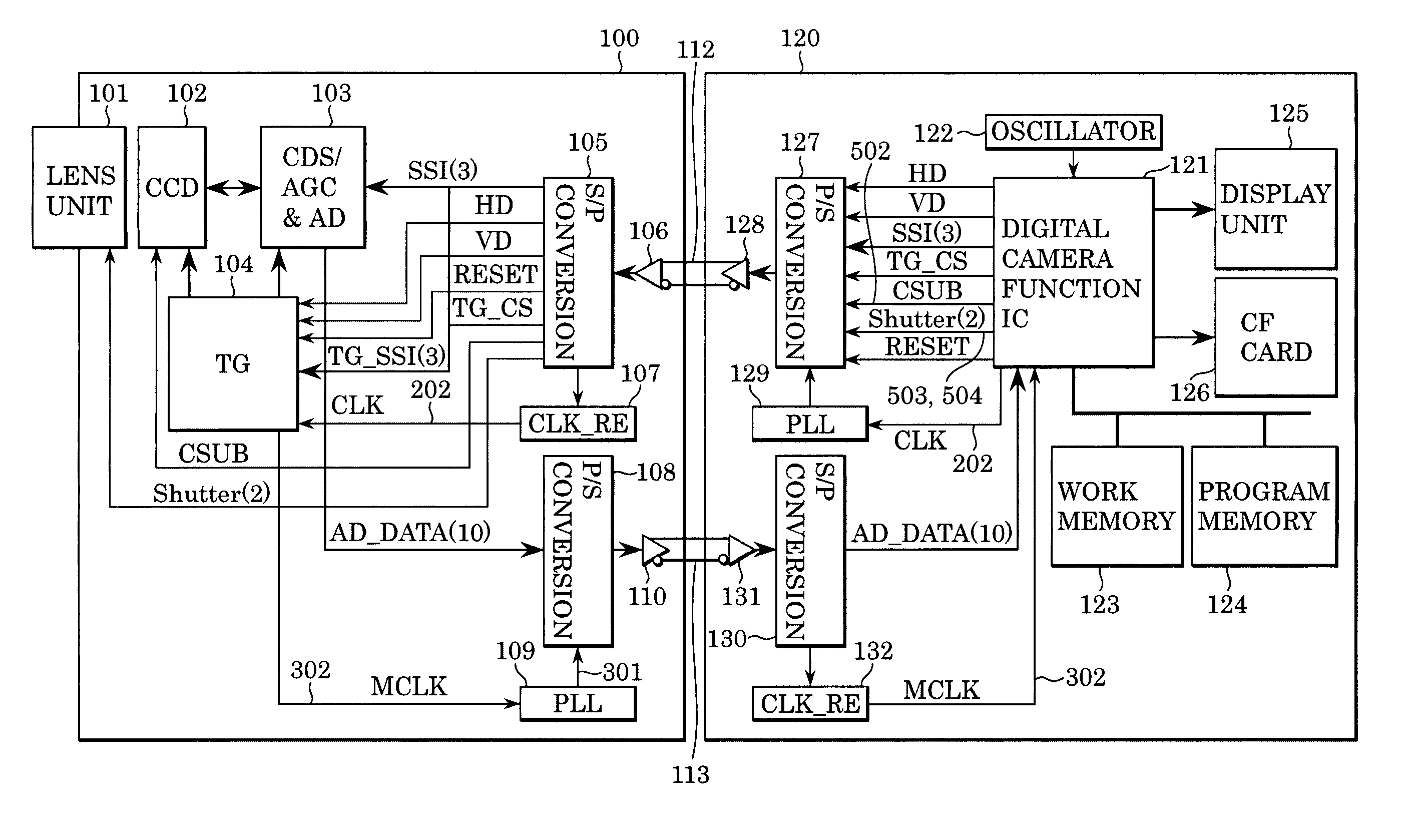
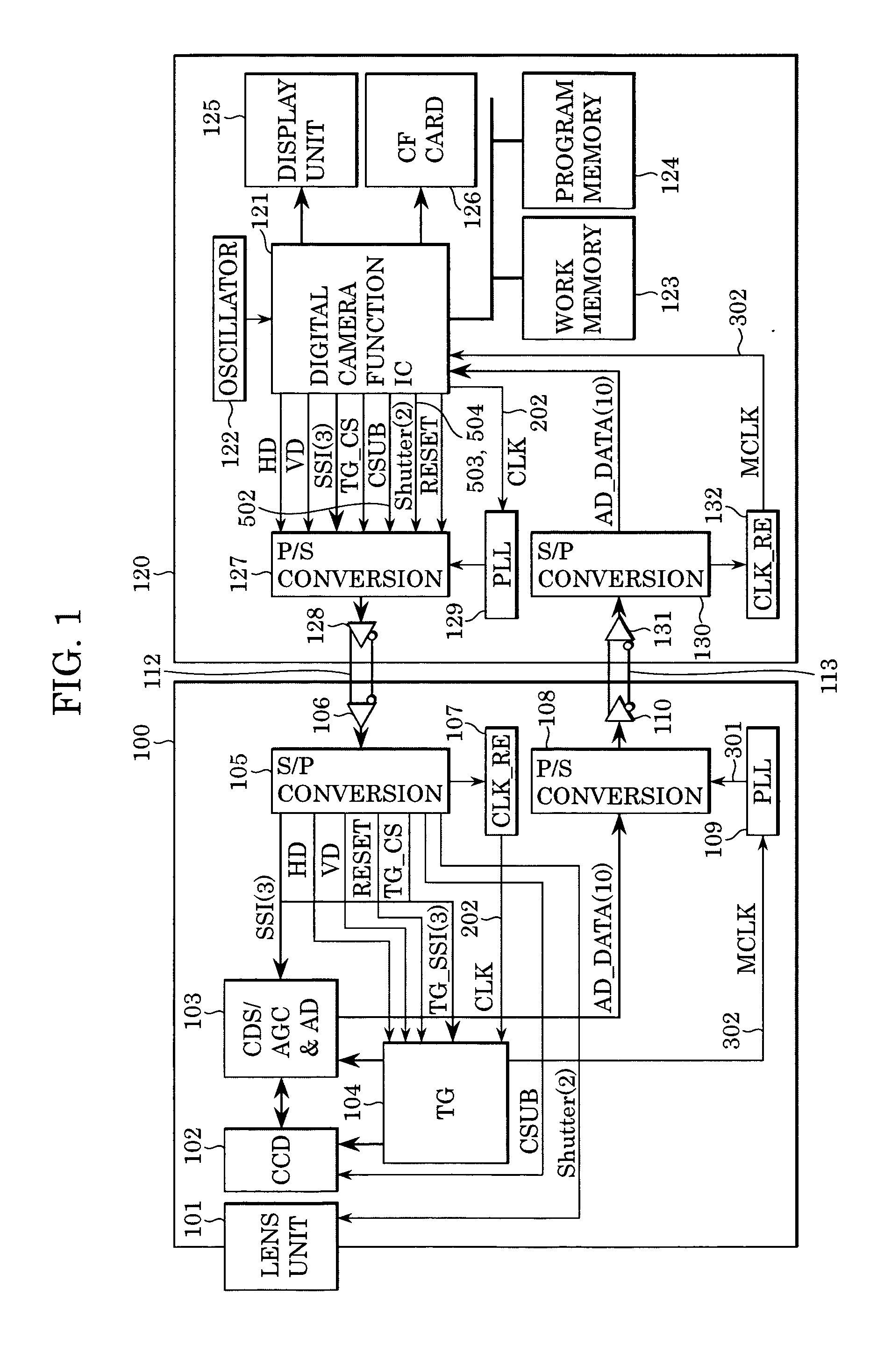
[0035]FIG. 1 is a block diagram illustrating the schematic configuration of a separate-head type image capturing system according to a first embodiment of the present invention.

[0036] In FIG. 1, reference numeral 100 denotes a camera unit separated from a main unit 120, 101 denotes a lens unit for inputting an image in a CCD 102, in which a shutter mechanism for performing open / close control using a solenoid valve is built. CCD 102 converts an image to be input from the lens unit 101 into electrical signals. Reference numeral 103 denotes a CDS / AGC&AD for gain-adjusting an analog signal to be output from the CCD 102, and converting the analog signal into a digital signal.

[0037] Reference numeral 104 denotes a timing generator (TG) for generating a timing signal for driving the CCD 102 and the CDS / AGC&AD 103. The timing generator 104 inputs a timing generator reference clock (CLK) 202 outputted from a digital camera function IC 121, supplies this signal, which is ½-divided, to the C...

second embodiment

[0074] With the above-described first embodiment, the CCD 102 and CDS / AGC&AD 103 are related to image display, the control signals are related to the timing generator 104, and the shutter control signals 503 and 504 are output from the digital camera function IC 121 to the parallel-to-serial converter 127. However, the same function may be realized by other configurations.

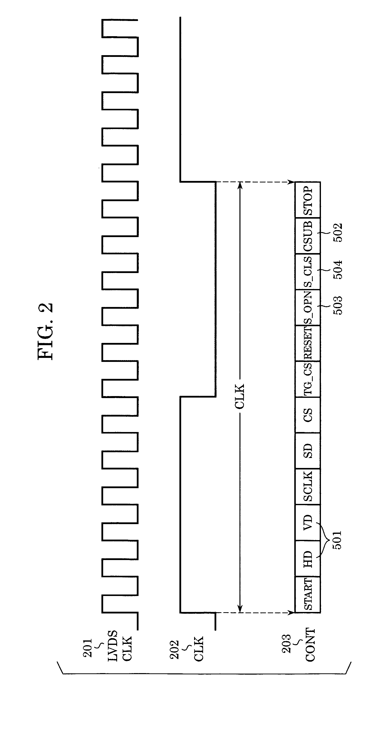
[0075] The present embodiment focuses attention on the fact that the shutter control signals 503, 504 and the board bias control signal (CSUB) 502 are synchronized with the vertical synchronization signal (VD) 501, the main unit 120 is provided with multiplex output means for multiplexing the shutter control signals 503, 504 and the board bias control signal (CSUB) 502 within the vertical synchronization signal (VD) 501 and outputting, and the camera unit 100 is provided with output analyzing means for separating this multiplexed signal into the original control signals, thereby realizing the same function as the ...

third embodiment

[0088] With the above-described first embodiment, the CCD and CDS / AGC&AD related to image display, the control signals related to the timing generator, and the shutter control signals are output from the digital camera function IC 121 to the parallel-to-serial converter 127. However, as high-pixelation of CCDs has advanced, building in auto-focus processing with focus motor control has become popular. Accordingly, a focus motor control signal can also be transmitted to the camera unit 100.

[0089] The present embodiment allows the focus motor control signal to be transmitted as well as the control signals to be transmitted in the aforementioned embodiments by increasing the number of bits available in the parallel-to-serial converter. In addition, the present embodiment allows a single parallel-to-serial converter to perform processing regardless of presence / absence of focus motor control without unnecessarily increasing the frequency of the serial transfer clock within the parallel-...


PUM


Abstract

An image capturing system includes an image-capturing unit and a main unit, capable of serial communication therebetween. The main unit generates a first clock signal, converts data to be transmitted to the image-capturing unit into serial data using the first clock signal, and transmits the serial data to the image-capturing unit. The image-capturing unit detects a serial transfer frequency from the received serial signal, reproduces the first clock signal, generates a second clock signal from the reproduced first clock signal, converts a taken image into serial data using the second clock signal, and transmits this data to the main unit. The main unit then reproduces the second clock signal from the serial data transmitted from the image-capturing unit, and utilizes the second clock signal to generate the first clock signal, thereby synchronizing the image-capturing unit and the main unit.

Description

BACKGROUND OF THE INVENTION [0001] 1. Field of the Invention [0002] The present invention relates to an image capturing system having a configuration wherein a camera unit and a main unit are separate, capable of serial communication between the camera unit and the main unit, and to a control method of the image capturing system. [0003] 2. Description of the Related Art [0004] In general, conventional image capturing systems (e.g., separate head type image capturing systems) where the camera unit and the main unit are separated, as disclosed in Japanese Patent Laid-Open No. 10-42176, are arranged (digital data separation type) such that the camera unit comprises a portion which handles the image capture process up to immediately before AD conversion output from a CCD. The camera unit is connected by a cable to the main unit, which performs AD conversion on the output from the CCD. Accordingly, in the event that a user wants to extend the distance between the camera unit and the main...

Claims


Application Information

Patent Timeline
IPC IPC(8): H04N5/225H04N5/232
CPCH04N5/23203H04N23/66
Inventor ENDO, YOSHIYUKI
Owner CANON KK
Why Eureka
Try Eureka