Image display apparatus

a technology of image display and display screen, which is applied in the direction of optical elements, instruments, printing, etc., can solve the problems of inacceptability, and deteriorating image quality, and achieve the effect of high contrast without deteriorating light use efficiency

Active Publication Date: 2005-08-18
JVC KENWOOD CORP A CORP OF JAPAN
View PDF1 Cites 22 Cited by
  • Summary
  • Abstract
  • Description
  • Claims
  • Application Information

AI Technical Summary

Benefits of technology

[0029] The image display apparatus according to the present invention can vary the focal length of the projection lens without passing unwanted light and without blocking necessary light, and therefore, can display images of high contrast without deteriorating the light use efficiency.
[0030] The image display apparatus according to the present invention can realize a flapping function by offsetting the projection lens from an optical axis. In connection with this function the image display apparatus can always optimally control the position of the aperture of the diaphragm in a flapping direction when conducting a focal length varying operation. With the focal length varying operation, the image display apparatus can maintain an optimum color balance adjusted by the color balance adjusting filter.

Problems solved by technology

For an image display apparatus having a focal-length-variable projection lens, it is not acceptable to simply arrange a diaphragm having an aperture whose shape is similar to the shape (for example, rectangle) of a condensed beam emitted from a fly-eye lens array optical system or from a rod integrator optical system.
This is because, when the focal length of the projection lens is changed, the diaphragm will pass excessive light (unwanted light) to deteriorate the quality of displayed images, or the diaphragm will block necessary light to deteriorate the light use efficiency.
In this case, unnecessary light passes through the excessive opening to deteriorate the quality of displayed images.
Then, the aperture of the projection lens at the long focus end is small (large F-number), and light from the illuminating optical system is insufficiently used to deteriorate the light use efficiency.

Method used


Image

  • Image display apparatus
  • Image display apparatus
  • Image display apparatus

Examples


first embodiment

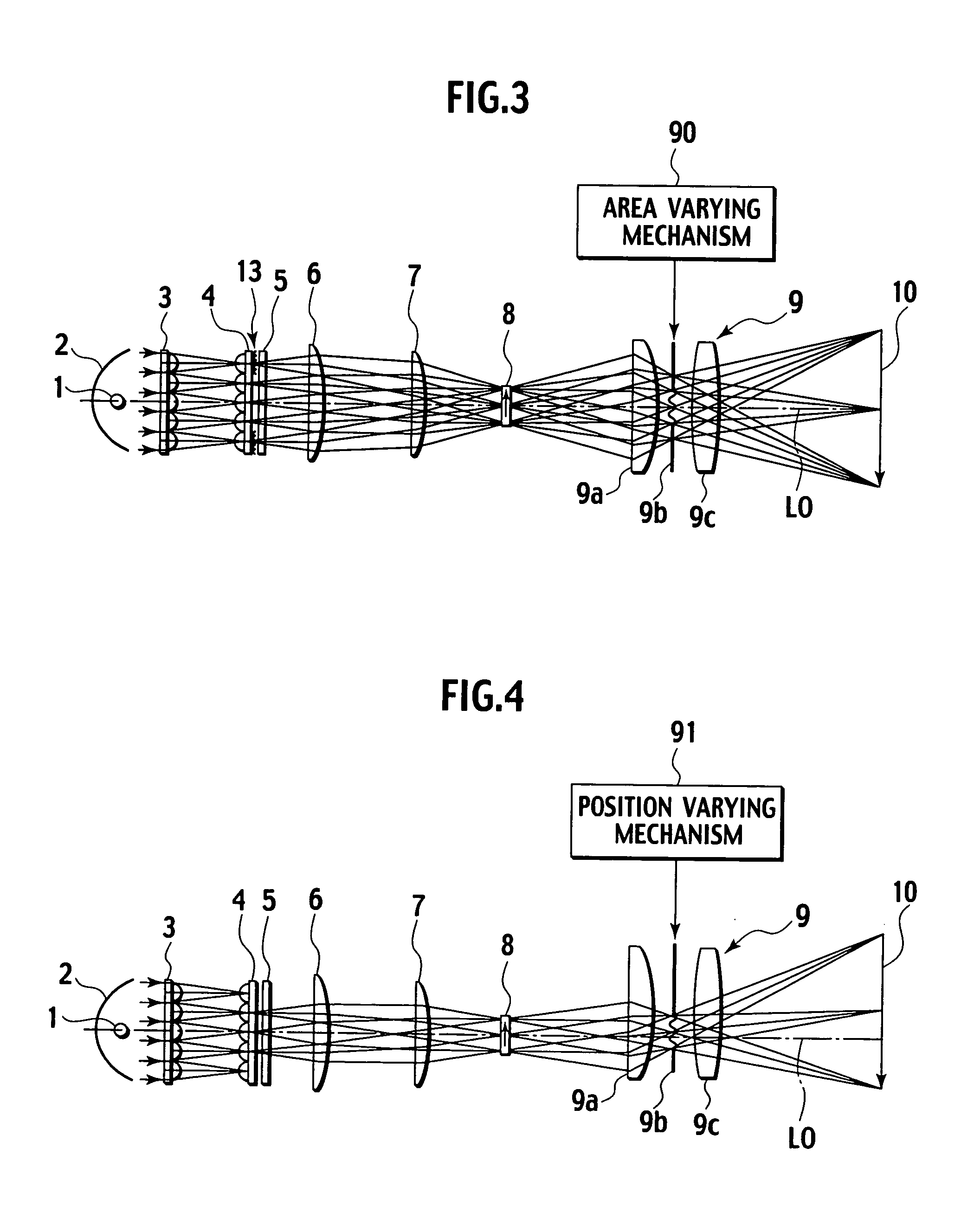
[0073]FIG. 3 is a plan view showing an image display apparatus according to a first embodiment of the present invention. In FIG. 3, the same parts as those of FIG. 1 are represented with like reference numerals and their explanations will not be repeated. A projection lens 9 shown in FIG. 3 is of a focal-length-variable type.

[0074] For the sake of simplicity, the image display apparatus of FIG. 3 is depicted as a monochromatic image display apparatus. In practice, the apparatus will be materialized as a color image display apparatus. Illumination light from a light source 1 is transmitted through first and second lens arrays 3 and 4. Part of the transmitted light distal from an optical axis L0 is passed through a color balance adjusting filter 13. The filter 13 blocks a predetermined wavelength range of the light to drop the level thereof and passes the remaining wavelength range of the light, to thereby adjust a color balance of images to be displayed. In this example, the filter ...

second embodiment

[0081]FIG. 4 is a plan view showing an image display apparatus according to a second embodiment of the present invention. In FIG. 4, the same parts as those of FIG. 1 are represented with like reference numerals and their explanations will not be repeated. A projection lens 9 shown in FIG. 4 is of a focal-length-variable type.

[0082] The image display apparatus according to the second embodiment has a flapping function. Namely, the optical axis (center axis) of the projection lens 9 is offset in parallel from the optical axis L0 of an illuminating optical system, or is inclined relative to the optical axis L0. The flapping function is useful to correctly display an image on a screen 10 when the image display apparatus is offset from a front position of the screen 10, or when the image display apparatus is inclined relative to a normal of the screen 10.

[0083] In FIG. 4, the optical axis of the projection lens 9 is offset in parallel from the optical axis L0 of the illuminating optic...

third embodiment

[0087]FIGS. 5 and 6 are plan views showing an image display apparatus according to a third embodiment of the present invention, in which FIG. 5 shows a focal-length-variable projection lens 9 being at a short focus end (wide end) and FIG. 6 shows the same at a long focus end (tele end).

[0088] According to the third embodiment, the projection lens 9 of the image display apparatus is a focal-length-variable lens (zoom lens). Varying a focal length is achieved by changing the distance between an entrance lens 9a and an exit lens 9c of the projection lens 9. The projection lens 9 consisting of the entrance lens 9a and exit lens 9c has a resultant focal length that is variable according to the distance between the entrance lens 9a and the exit lens 9c.

[0089] When the distance between the entrance lens 9a and the exit lens 9c is changed to change a resultant focal length, a pupil position also changes in the direction of an optical axis L0. To prevent the pupil position from moving in r...


PUM


Abstract

An image display apparatus includes a diaphragm (9b) arranged at a pupil position. The shape of an aperture of the diaphragm (9b) is similar to the shape of a light source image formed by an illuminating optical system at the pupil position. An area varying mechanism (90) varies the area of the aperture of the diaphragm (9b) in response to a focal length varying operation of a projection lens (9). This prevents an excessive opening from being formed around a light source image cast by the illuminating optical system, thereby preventing the deterioration of displayed images due to unwanted light that may pass through the excessive opening.

Description

FIELD OF THE INVENTION [0001] The present invention relates to an image display apparatus that modulates light flux with a spatial light modulator such as a liquid crystal display element or a liquid crystal light valve and projects the modulated light flux onto a screen. BACKGROUND OF THE INVENTION [0002] Front-projection-type image display apparatuses are gradually spreading due to widespread personal computers and digital television broadcasting. [0003] A typical example of the front-projection-type image display apparatus is a three-panel color projector employing three spatial light modulators made of, for example, liquid crystal display elements. The three-panel color projector employs a strong light source such as a metal halide lamp to emit a white beam. The white beam is separated into three primary-color beams, which are guided to the spatial light modulators, respectively. The spatial light modulators modulate the three primary-color beams according to image signals. The ...

Claims


Application Information

Patent Timeline
Patent Type & Authority Applications(United States)
IPC IPC(8): G02B5/00G02B27/14G03B21/00G03B21/14
CPCG02B5/005G02B27/102H04N9/315G03B21/14H04N9/3105G02B27/145G03B21/208
Inventor KOBAYASHI, MANABUSUZUKI, TETSUJIAIZAKI, TAKATSUGUTAKAHASHI, RYUSAKU
Owner JVC KENWOOD CORP A CORP OF JAPAN
Why Eureka
Try Eureka