Backlight module and heat dissipation structure thereof

Active Publication Date: 2005-08-18
AU OPTRONICS CORP
View PDF5 Cites 79 Cited by
  • Summary
  • Abstract
  • Description
  • Claims
  • Application Information

AI Technical Summary

Benefits of technology

[0007] Accordingly, an object of the invention is to provide a heat dissipation structure with improved case of assembly and dissipation efficiency. The heat dissipation structure of the invention comprises a heat conducting portion thermo-conductively con

Problems solved by technology

However, such structure is not easily assembled and can damage the LED du

Method used


Image

  • Backlight module and heat dissipation structure thereof
  • Backlight module and heat dissipation structure thereof
  • Backlight module and heat dissipation structure thereof

Examples


Embodiment Construction

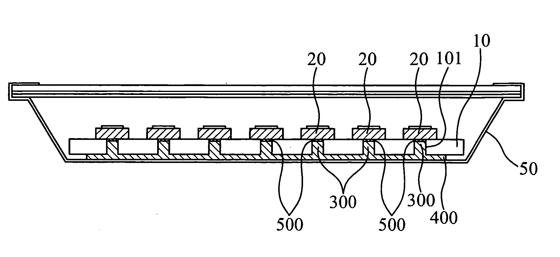
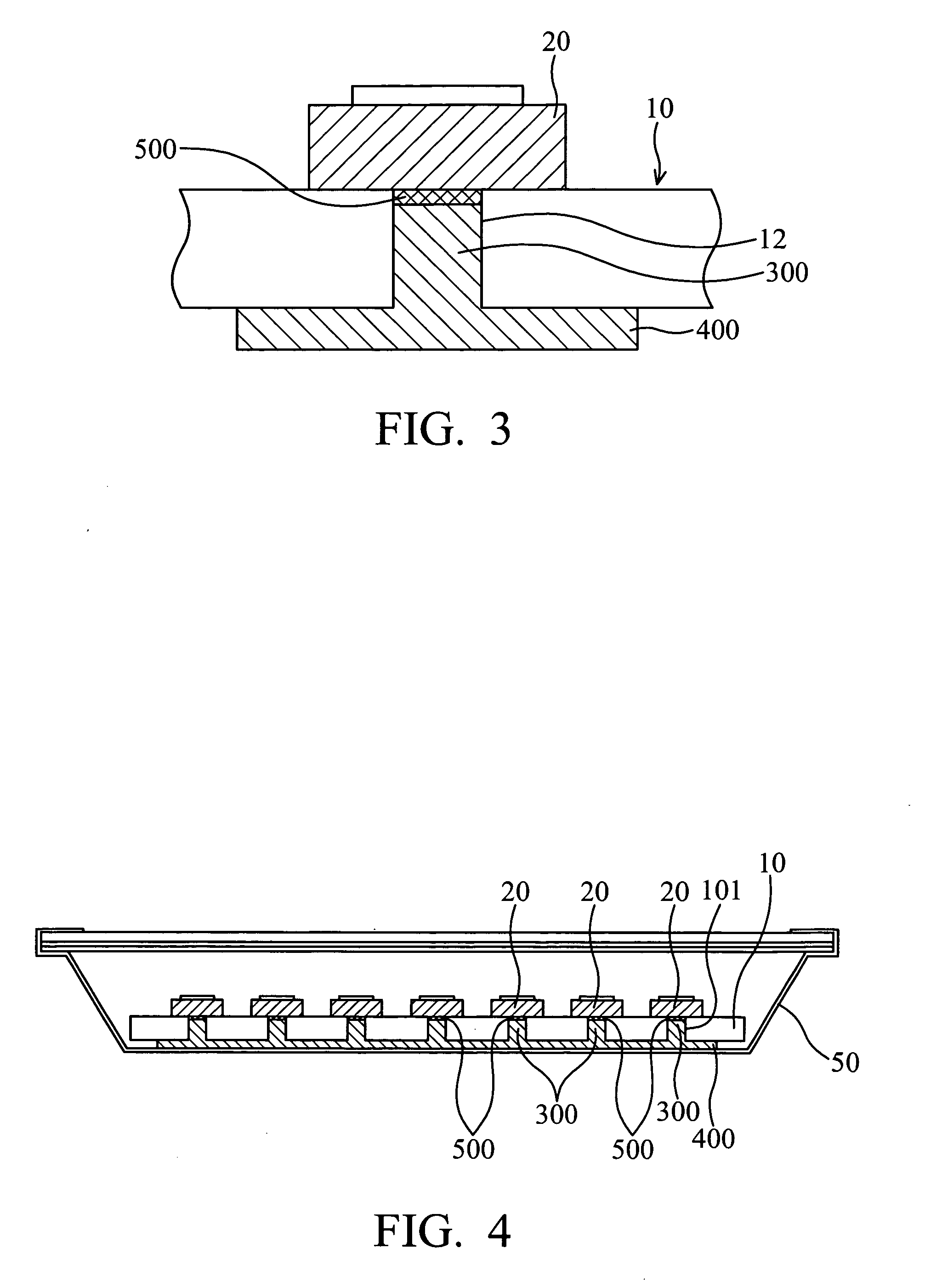
[0021] Referring to FIG. 3, an LED 20 is disposed on and electrically connected to a printed circuit board 10. The heat dissipation structure in the invention comprises a heat conducting column 300 connected to the back of the LED 20 with one end thereof via a thermal conductive element 500 and further comprises a heat dissipating plate 400 connected to the other end of the heat conducting column 300 and positioned near the back of the circuit board 10. The heat dissipating plate 400 and the heat conducting column 300 are formed integrally and configured. Thereby, the heat of the LED 20 is conducted along the thermal conductive element 500 and the heat conducting column 300 to the heat dissipating plate 400.

[0022] The heat conducting column 300 is made of metal such as copper or aluminum or plastic with high thermal conductivity. The thermal conductive element 500 can be a soft thermal conductive pad or paste contacting the heat conducting column 300 and the LED 20. Thereby the the...


PUM


Abstract

A backlight module and heat dissipation structure thereof. The heat dissipation structure is used for a backlight module which comprises a circuit board having a through hole with a light emitting diode (LED) corresponding thereto and disposed on one side of the circuit board. The heat dissipation structure comprises a heat conducting portion thermo-conductively connected to the LED and positioned in the through hole, a thermal conductive element disposed between the heat conducting portion and the LED, and a heat dissipating portion thermo-conductively connected to the heat conducting portion. Heat from the LED is conducted through the thermal conductive element and the heat conducting portion to the heat dissipation portion.

Description

BACKGROUND OF THE INVENTION [0001] 1. Field of the Invention [0002] The present invention relates to a heat dissipation structure for a backlight module, and in particular to a heat dissipation structure with improved dissipation efficiency and easier assembly in a backlight module. [0003] 2. Description of the Related Art [0004] Light emitting diodes (LED) often used as a light source for conventional backlight modules, requiring heat dissipation. As shown in FIG. 1, an LED 20 is disposed on a circuit board 10 having a through hole 12. Heat dissipation column 30 is soldered to the LED and positioned in the through holes for efficient heat dissipation. However, such structure is not easily assembled and can damage the LED during assembly. [0005] Another conventional heat dissipation structure is disclosed in U.S. Pat. No. 5,857,767 and shown in FIG. 2. In addition to the heat dissipation column 30 as in FIG. 1, a heat dissipation plate 40 with fins is attached to the heat dissipatio...

Claims


Application Information

Patent Timeline
IPC IPC(8): F21K99/00F21V29/00F21V29/505G02F1/1333H05K1/02
CPCF21K9/00F21V29/004F21Y2101/02G02B6/0073H05K2201/10416G02F1/133603G02F2001/133628H05K1/0204H05K2201/10106G02B6/0085F21Y2115/10G02F1/133628F21V29/89
Inventor TSAI, YI-SHIUAN
Owner AU OPTRONICS CORP
Why Eureka
Try Eureka