

Planar light source
- Summary
- Abstract
- Description
- Claims
- Application Information
AI Technical Summary
Benefits of technology
Problems solved by technology
Method used
Image

Examples
first embodiment
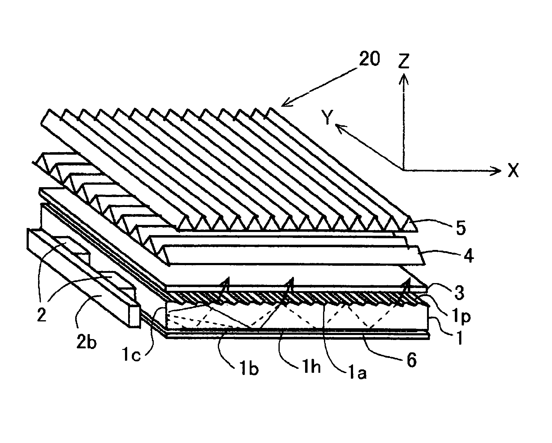
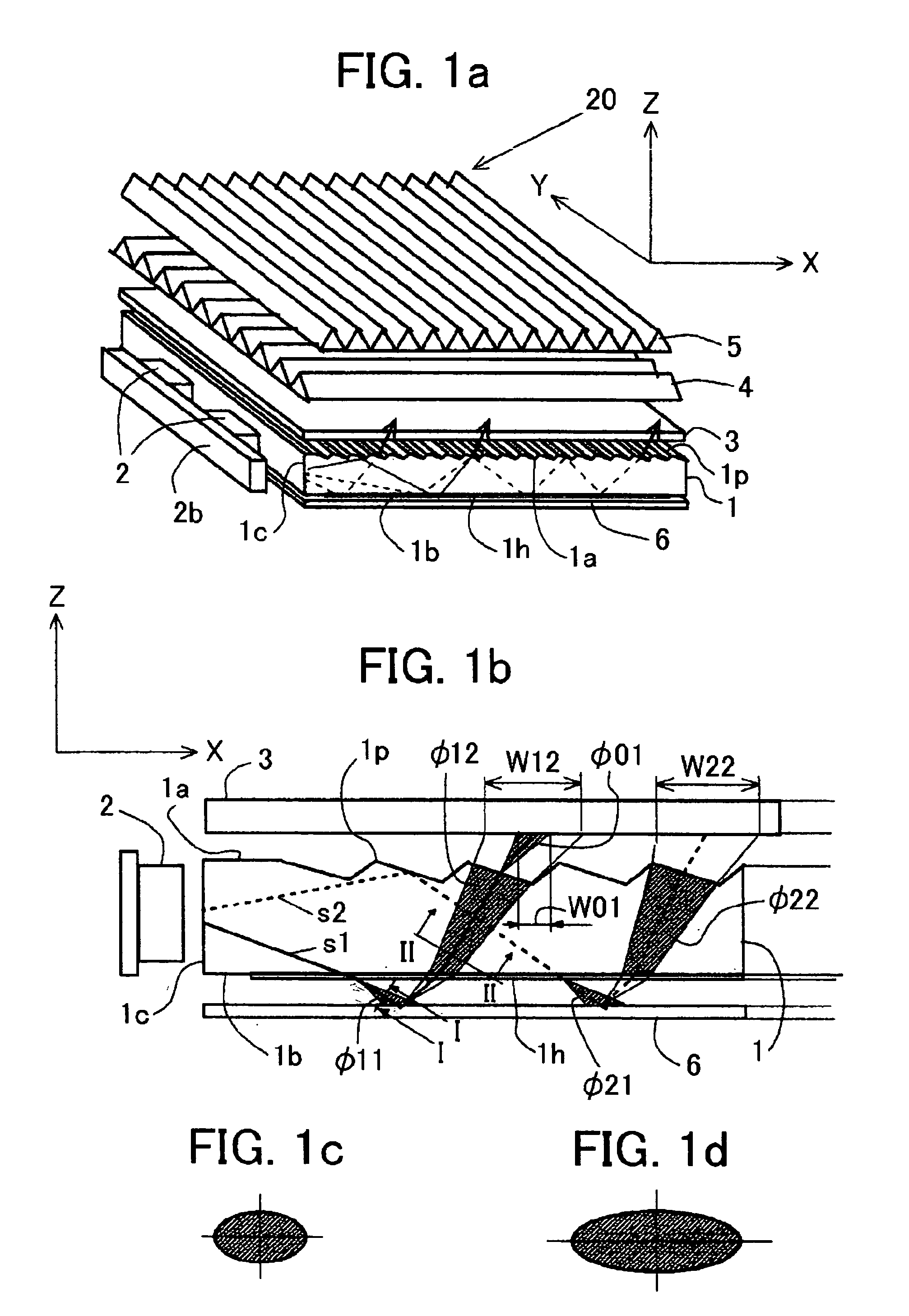
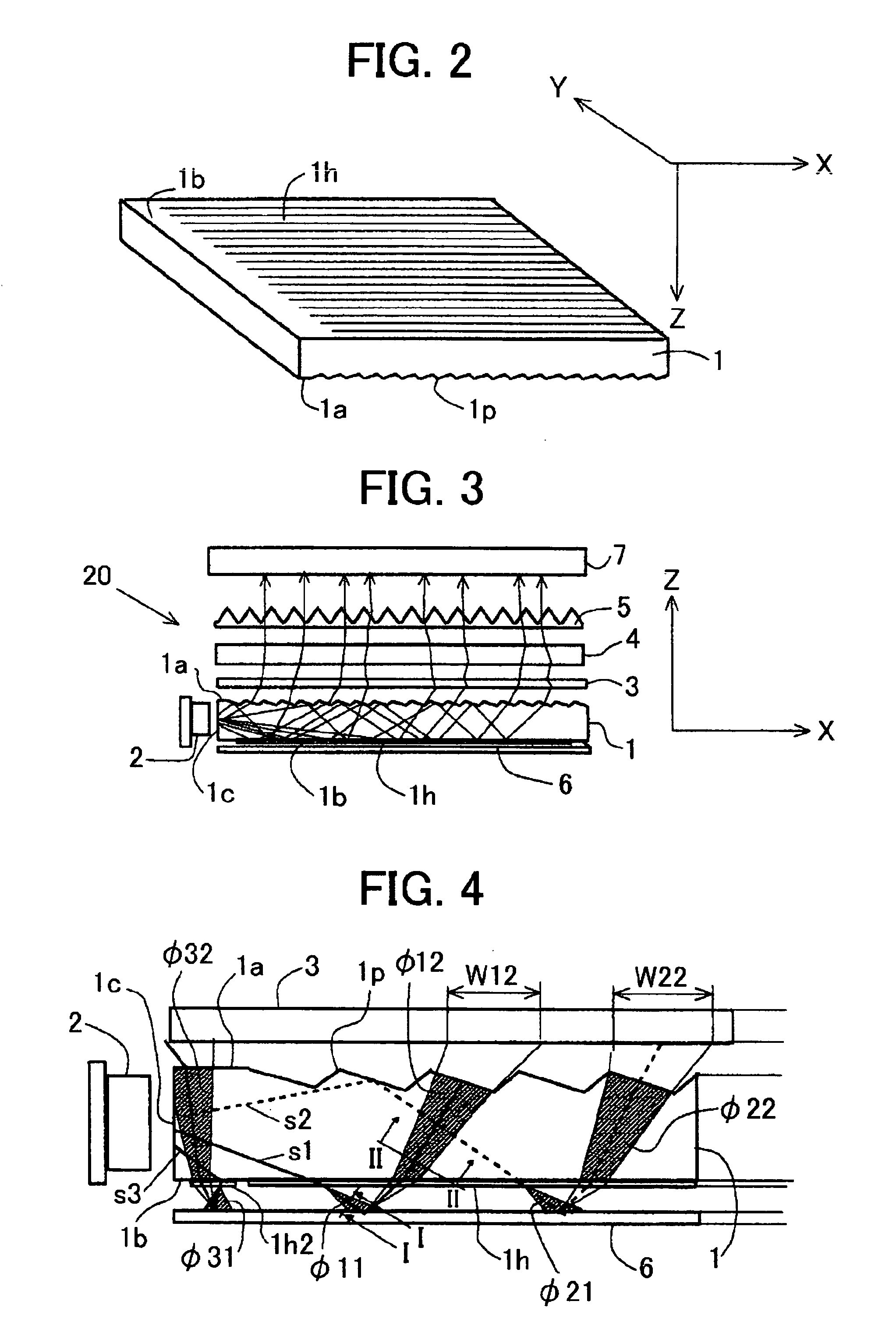
[0065] a planar light source of the present invention is described hereinafter with reference to FIGS. 1a to 1d, FIG. 2, and FIG. 3. FIG. 1a is a perspective view showing the entire light source, FIG. 1b is an illustration showing the operation of a light guide plate provided in the light source, FIGS. 1c and 1d are diagrams describing the operation of the planar light source, FIG. 2 is a perspective view of a light guide plate provided in the light source, and FIG. 3 is a sectional view of the planar light source explaining the illuminating operation thereof.
[0066] Referring to FIG. 1a, a planar light source 20 comprises a pair of LEDs 2, a light guide plate 1, a diffusion panel 3, a Py prism sheet 4, a Px prism sheet 5, and a reflection plate 6. The reflection plate 6, light guide plate 1, diffusion plate 3, prism sheets 4 and 5 are stacked.
[0067] The light guide plate 1 is made of a transparent plastic and has an upper surface 1a, lower surface 1b and front side 1c. The LEDs 2 a...
second embodiment
[0075] In accordance with the second embodiment, the light beams, the output angles of which are limited within a desired angle, enter the entire area of the diffusion panel 3 so that the luminance of the illuminating light emitted from the planar light source is improved while maintaining the level of brightness.
[0076] Referring to FIG. 5, showing the third embodiment of the present invention, a light guide plate 11 has a flat horizontal upper surface 11a and a lower surface 11b inclining upward as the distance from a front side 11c increases. The lower surface 11b has a first anisotropic diffusion surface 11h and a second anisotropic diffusion surface 11h2 adjacent the front side 11c having the same characteristics as the second anisotropic diffusion surface 1h2 of the second embodiment. A third anisotropic diffusion surface 11h3 is formed on the upper surface 11a at an appropriate position adjacent the front side 1c. The third anisotropic diffusion surface 11h3 has the same chara...
PUM
 Abstract
Description
Claims
Application Information