Fabric seam formation by radiation welding process

Inactive Publication Date: 2005-08-18
INVISTA NORTH AMERICA R L
View PDF6 Cites 20 Cited by
  • Summary
  • Abstract
  • Description
  • Claims
  • Application Information

AI Technical Summary

Benefits of technology

[0010] The present invention overcomes at least some problems associated with the prior art by providing a met

Problems solved by technology

Adhesive bonding is slower and more costly than sewing.
Under the high pressure of airbag inflation, however, such RF welded seams are known to be mechanically inadequate.
Applicants have found the prior art seam formation methods disadvantageous in several modes of performance.
First, the prior art sewn seam is not suffici

Method used


Image

  • Fabric seam formation by radiation welding process
  • Fabric seam formation by radiation welding process

Examples


invention example

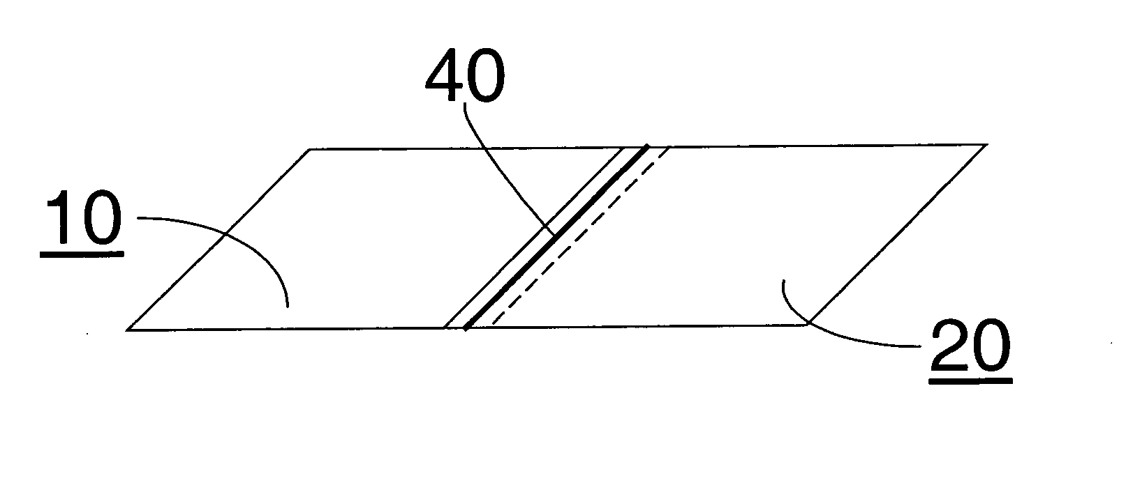
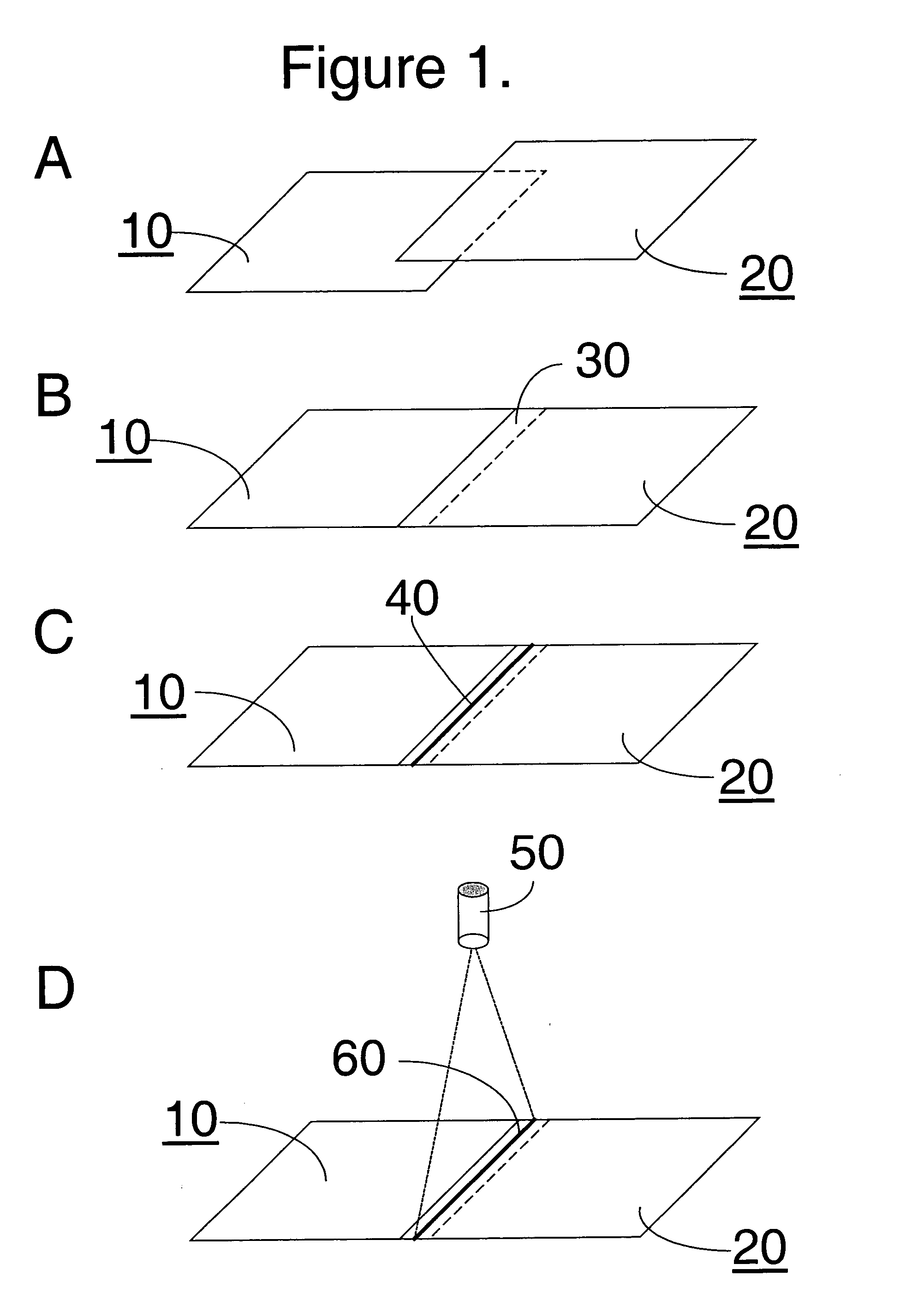
[0035] Part 1. In this example of the invention, the same fabric woven used in the comparative example was used to construct a cushion form with continuous seams using the laser welding process, also included was a tubulation portion through which inflation gas could be introduced. The laser used to weld the seams was a ROFIN-BAASEL one kilowatt diode laser (obtained from ROFIN-BASSEL, 330 Codman Hill Road, Boxborough, Mass., USA 01719) operating in continuous mode at a wavelength of 940 nanometers; the beam width was 10 millimeters. A cyanine dye with a near infrared absorption maximum of about 785 nanometers (nm) was applied in a line over a lapped portion of the two fabric ends. No more than 50 grams of dye per square meter of fabric exposed to the laser was applied. The laser was scanned at 2 to 10 meters per minute and power in the range of 200 to 1000 Watts. This laser welded seam was measured for gas tightness and seam integrity by the test methods.

[0036] In comparison, the ...


PUM

PropertyMeasurementUnit
Forceaaaaaaaaaa
Forceaaaaaaaaaa
Poweraaaaaaaaaa

Abstract

A method for forming a radiation, such as laser, welded point of attachment between at least two fabric pieces, such as ends, is provided. The method comprises the steps of lapping the fabric pieces to be attached; applying to the lapped fabric pieces in a region where the fabric pieces are to be attached a radiation, preferably an infrared energy, absorbing ink; and exposing the ink applied region of lapped fabric pieces to a source of radiation in the wave length absorbed by the radiation absorbing ink. In the case of an infrared absorbing ink, a laser light power has been applied in the range of 200 to 1000 Watts while scanning laser light along the ink applied region at a rate of one to twenty-five meters per minute. The method provides a fabric construction useful as an air bag, a gas inflatable safety cushion or curtain or in other applications, such as articles of apparel.

Description

CROSS-REFERENCE TO RELATED APPLICATION [0001] This application claims benefit of priority from Provisional Application No. 60 / 546,083 filed Feb. 18, 2004.FIELD OF THE INVENTION [0002] The present invention relates to a method for joining fabrics, or seam formation, and fabrics joined by the inventive method. More particularly it relates to seam formation using radiation in the presence of a radiation absorbing ink, generally laser light, to weld two or more fabric pieces, and fabric pieces joined by seams formed using radiation. Most particularly this invention relates to a method of seam formation in high performance fabrics which provides a substantially gas-tight fabric seam of high mechanical strength, and the high performance fabrics joined therefrom. BACKGROUND OF THE INVENTION [0003] It is long known to form seams when joining different fabrics, or different pieces of fabrics. Fabrics are joined together for a multitude of purposes. For example, fabrics are joined to form app...

Claims


Application Information

Patent Timeline
IPC IPC(8): A47H23/02A41D27/24B29C35/08B29C65/00B29C65/14B29C65/16B60R21/16D06H5/00
CPCA41D27/245Y10T428/19B29C65/1406B29C65/1412B29C65/1416B29C65/1425B29C65/1454B29C65/1483B29C65/1616B29C65/1654B29C66/1122B29C66/43B29C66/729B29C2035/0822B29K2067/00B29K2075/00B29K2077/00B29K2223/00B29K2313/00B29L2022/02B29L2022/027B29L2031/48B29C65/1612B29C65/1674B29C65/1683B29C65/14B29C66/71B29C66/73921B29K2023/00A47G9/10A47G9/1009A47G2009/1018
Inventor BARNES, JOHN A.BUDD, CAROL ANNWESTOBY, SCOTT
Owner INVISTA NORTH AMERICA R L
Why Eureka
Try Eureka