Peel-away catheter shaft

a catheter shaft and peeling technology, applied in the field of catheter systems, can solve the problems of reducing the tear resistance of the outer jacket, and achieve the effect of reducing the tear resistance of the shaft wall

Inactive Publication Date: 2005-08-18
CARDIAC PACEMAKERS INC
View PDF60 Cites 82 Cited by
  • Summary
  • Abstract
  • Description
  • Claims
  • Application Information

AI Technical Summary

Benefits of technology

[0005] The present disclosure describes a peel-away shaft for a guiding catheter. In one embodiment, a catheter shaft includes a shaft wall defining an open lumen of the catheter shaft. A peel-away region is defined over at least a partial length of the cath

Problems solved by technology

The peel-away feature of the outer jacket reduces the tear

Method used


Image

  • Peel-away catheter shaft
  • Peel-away catheter shaft
  • Peel-away catheter shaft

Examples


Embodiment Construction

[0020] In the following description of the illustrated embodiments, references are made to the accompanying drawings which form a part hereof, and in which is shown by way of illustration, various embodiments in which the invention may be practiced. It is to be understood that other embodiments may be utilized, and structural and functional changes may be made without departing from the scope of the present invention.

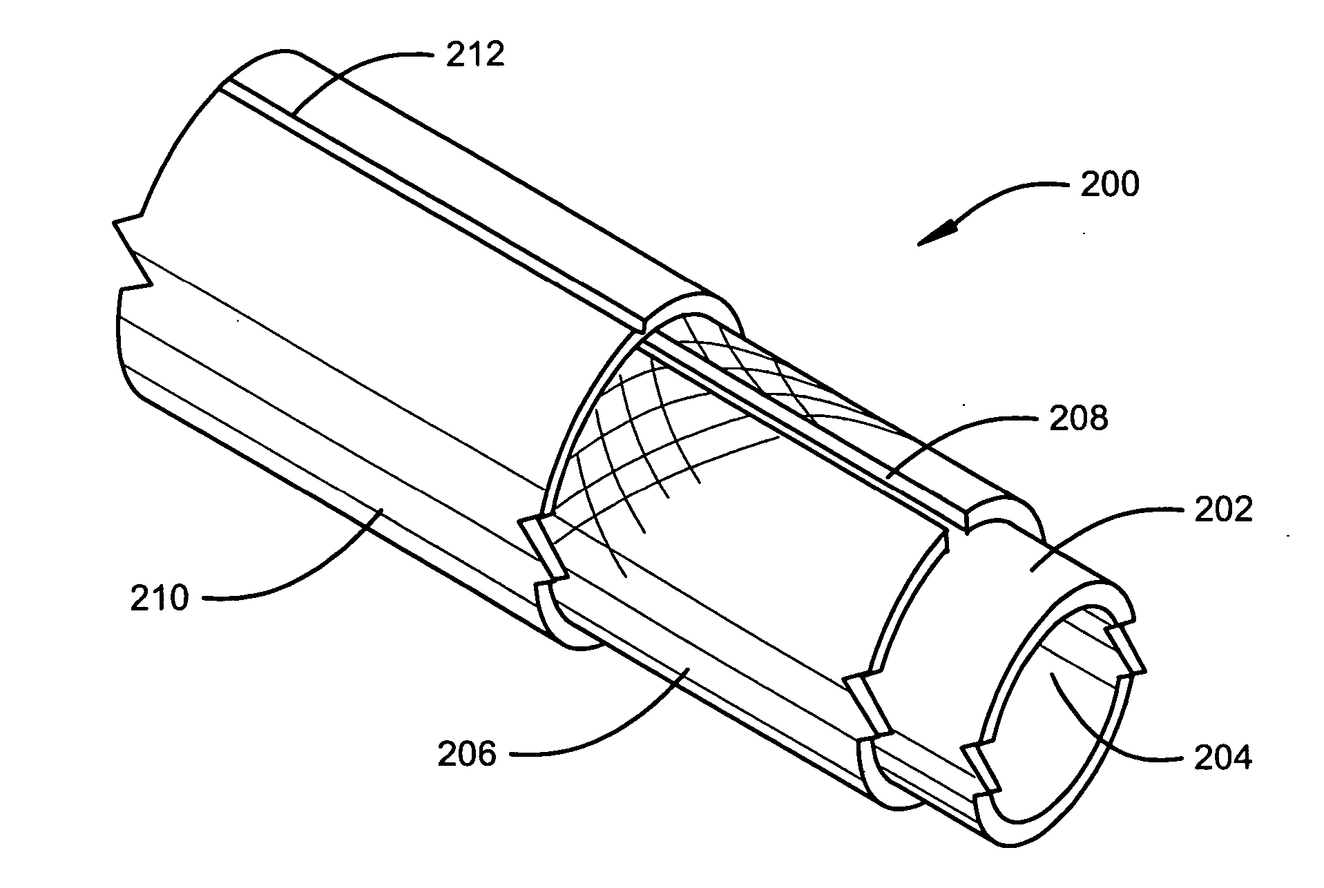
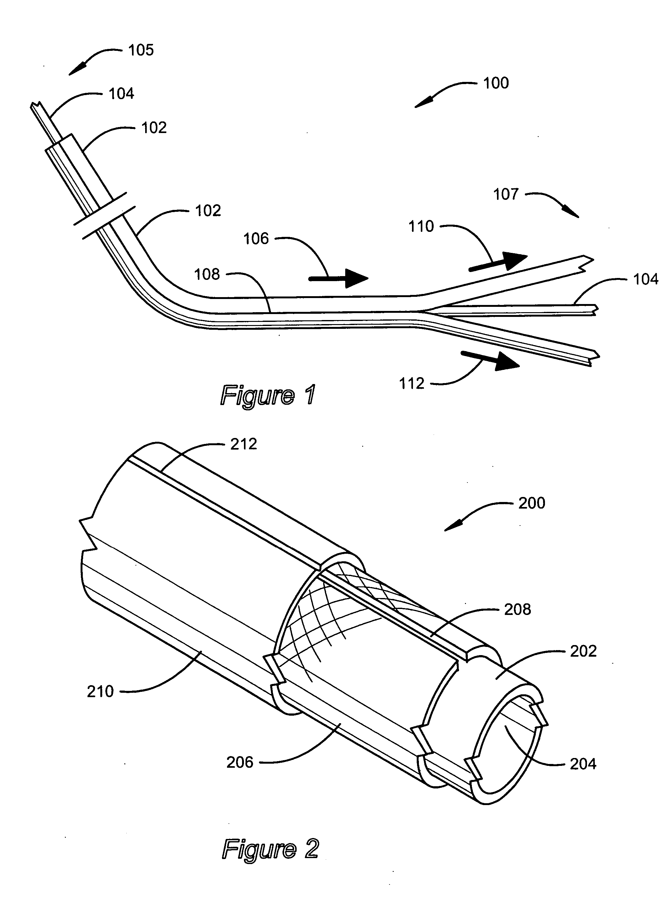
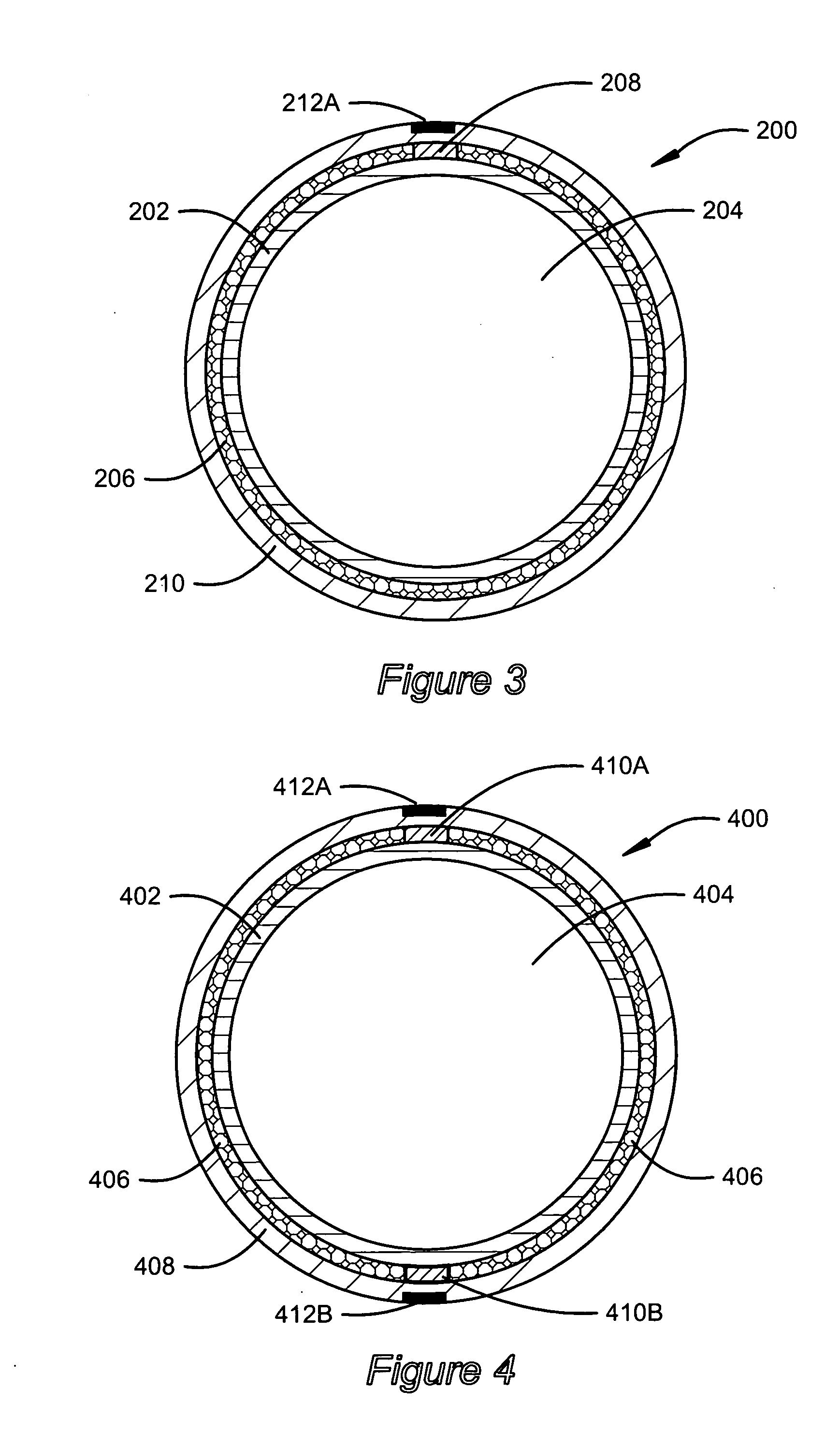
[0021] In broad and general terms, the present invention relates to a catheter shaft that provides the benefits of a braided shaft wall construction while allowing the shaft to be easily peeled away when being removed from the body following a medical procedure. This shaft construction may be useful in many applications, particularly where the catheter is used to guide an implantable payload that is intended to be left in place after the procedure is complete. This type of payload may include implantable leads, as well as measuring or monitoring apparatus. The present ...


PUM


Abstract

A peel-away shaft for a guiding catheter includes a shaft wall defining an open lumen of the catheter shaft. A peel-away region is defined over at least a partial length of the catheter shaft. A braid substantially encompasses the open lumen. The braid includes a region of discontinuity extending along the peel-away region. The region of discontinuity of the braid reduces the tear resistance of the shaft wall along the peel-away region.

Description

FIELD OF THE INVENTION [0001] The invention relates generally to catheter systems, and, more particularly, to catheters having peel-away shafts. BACKGROUND [0002] Catheters are commonly used in medical procedures for providing access to a patient's internal anatomy. Catheters can be used to assist in a wide range of procedures, including ablation, drug treatments, measurement, mapping, and device implantation. In many procedures, catheters are used to locate and cannulate vessels in support of the procedure. Cannulating heart vessels may require navigating a small diameter, flexible guide through the body into a destination vessel, such as those in the heart. Once the destination vessel is reached, the catheter can act as a conduit for insertion of payloads into the vessel. Catheters used in this manner are commonly referred to as guide catheters. [0003] Guide catheters are typically specially adapted for a particular type of procedure. For example, guide catheters adapted for impla...

Claims


Application Information

Patent Timeline
IPC IPC(8): A61M25/06
CPCA61M25/0668
Inventor WEBLER, WILLIAM EARL
Owner CARDIAC PACEMAKERS INC
Why Eureka
Try Eureka