Helical guide and advancement flange with radially loaded lip

a technology which is applied in the direction of prosthesis, ligaments, osteosynthesis devices, etc., can solve the problems of implant present special problems, difficult to solve, and the surgeon installing the implant presents a number of problems, so as to facilitate the capture and reduction of spinal fixation rods, improve the and improve the effect of helical guide and advancement flang

Active Publication Date: 2005-08-18
JACKSON
View PDF99 Cites 241 Cited by
  • Summary
  • Abstract
  • Description
  • Claims
  • Application Information

AI Technical Summary

Benefits of technology

[0024] The principal objects of the present invention include: providing an improved helical guide and advancement flange structure for guiding and advancing an inner member into an outer member; providing, particularly, improvements in helical guide and advancement flanges incorporating radially loaded lip and groove contours; providing such flange structure wherein the outer member is subject to being splayed in reaction to advancement and strong torquing of the inner member within the outer member and wherein an inner flange of the inner member and an outer flange of the outer member are particularly configured to cooperate in such a manner as to resist such splaying; providing such flange structure in which the inner and outer flanges are provided with contours including mutually facing surfaces which radially engage when the inner member is advanced into the outer member to resist splaying of the outer member; providing such flange structure in which anti-splay contours are formed on a trailing load flank of each flange to form an anti-splay lip near a crest region of the inner flange and a cooperating anti-splay groove near a root region of the outer flange; providing such flange structure in which the anti-splay contours are alternatively applied to a leading stab flank of each flange to form an anti-splay lip near a crest region of the inner flange and a cooperating anti-splay groove near a root region of the outer flange; providing such flange structure in which the anti-splay contours are alternatively formed on both the load and stab flanks of each flange to form anti-splay lips near a crest region of the inner flange and cooperating anti-splay grooves near a root region of the outer flange; providing such flange structure in which proportioning of mutual axial stresses on the engaged flanged can be controlled by selectively adapting the mutual angles of the engaged load flanks relative to a helical axis in such a manner as to control the region of engageme

Problems solved by technology

Medical implants present a number of problems to both surgeons installing implants and to engineers designing them.
These are normally conflicting goals, and often difficult to resolve.
One type of implant presents special problems.
While the open headed devices are often necessary and preferred for usage, there is a significant problem associated with them.
However, such threaded plugs have encountered problems in that they produce radially outward forces that lead to splaying of the arms or at least do not prevent splaying that in turn may lead to loosening of parts and failure of the implant.
For example, the arms were significantly strengthened by increasing the width of the arms by many times. This is undesirable since it leads to

Method used


Image

  • Helical guide and advancement flange with radially loaded lip
  • Helical guide and advancement flange with radially loaded lip
  • Helical guide and advancement flange with radially loaded lip

Examples


Embodiment Construction

[0047] As required, detailed embodiments of the present invention are disclosed herein; however, it is to be understood that the disclosed embodiments are merely exemplary of the invention, which may be embodied in various forms. Therefore, specific structural and functional details disclosed herein are not to be interpreted as limiting, but merely as a basis for the claims and as a representative basis for teaching one skilled in the art to variously employ the present invention in virtually any appropriately detailed structure.

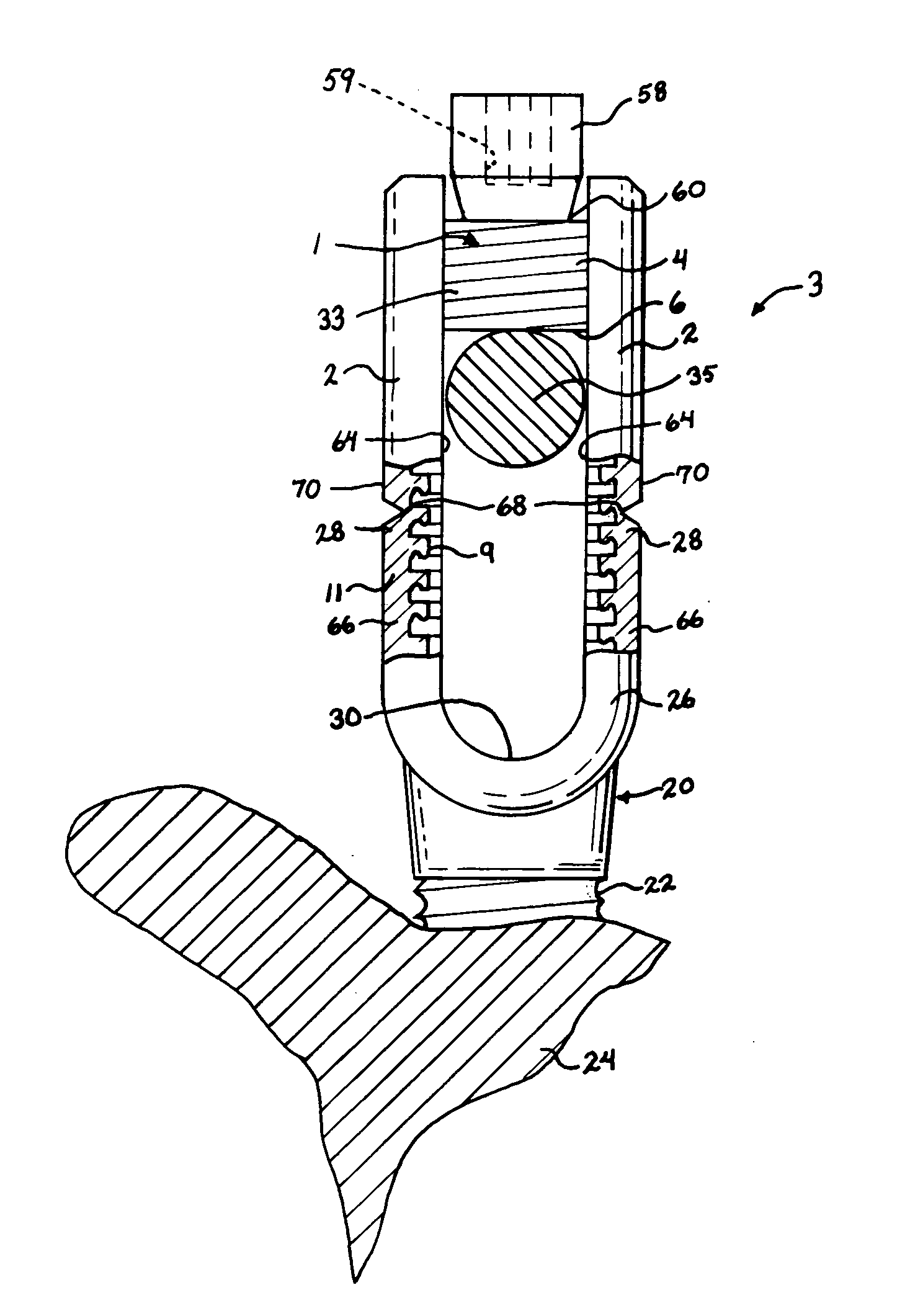
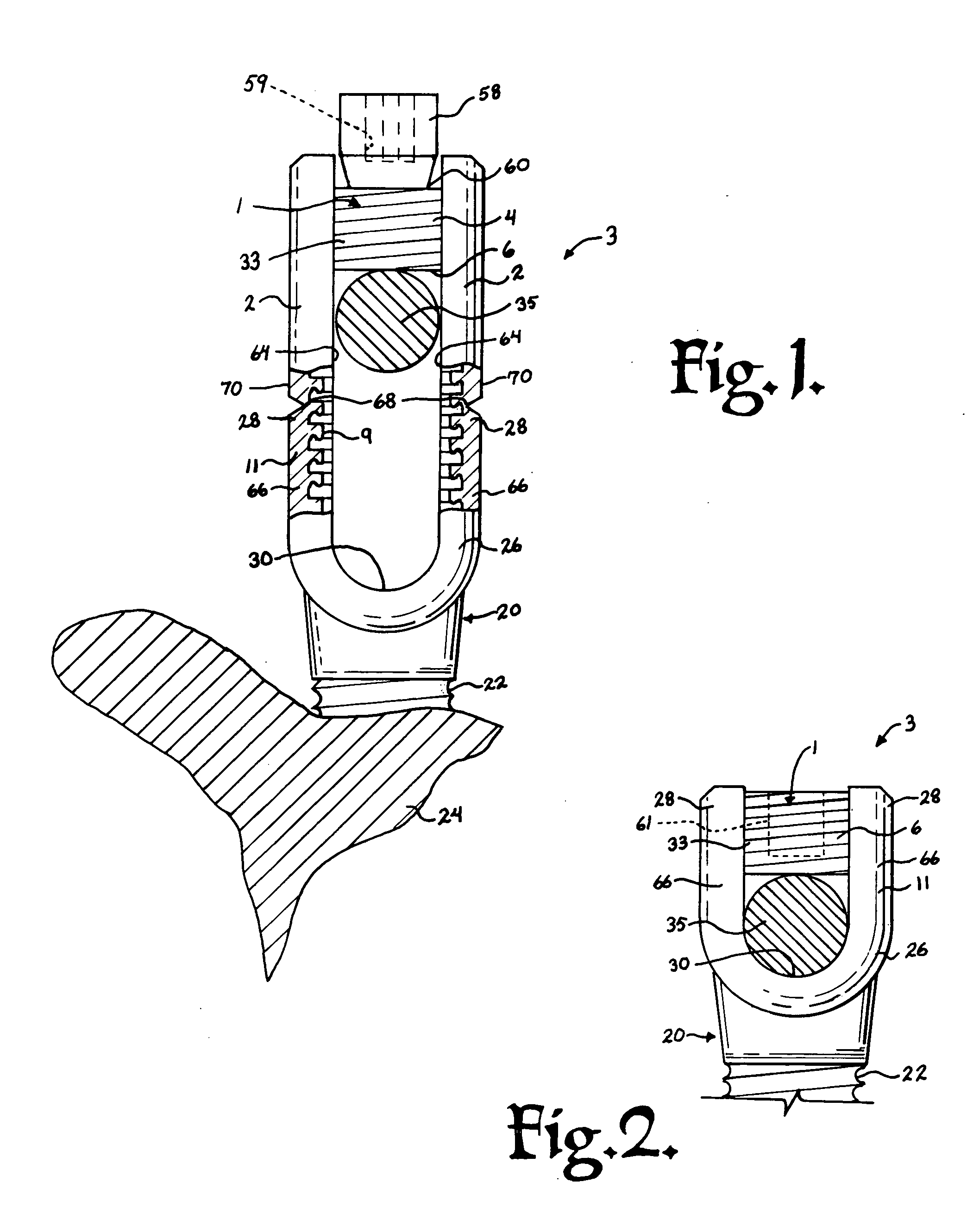
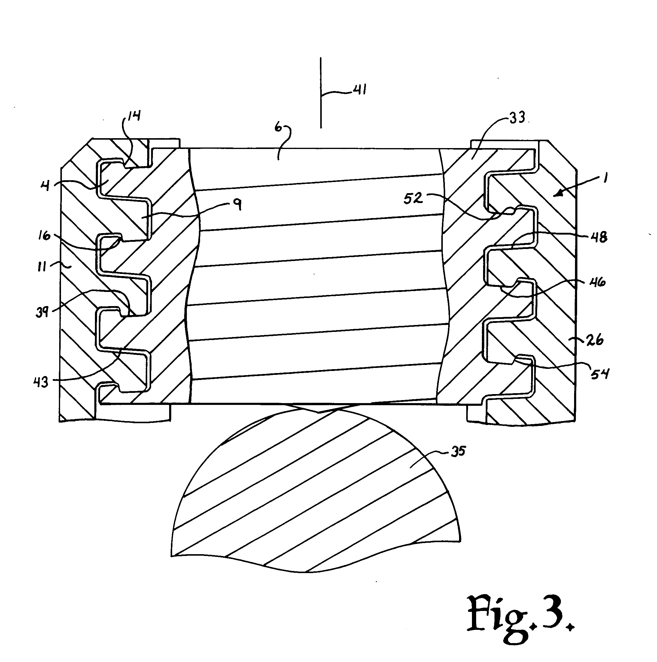
[0048] Referring to the drawings in more detail, the reference numeral 1 generally designates a helical guide and advancement flange structure with radially loaded lips and grooves incorporated in a medical implant 3 and embodying the present invention. The implant 3 can be of a fixed or monoaxial nature or, alternatively, it can have a polyaxial mechanism. The flange structure, or flange form, 1 generally includes an inner flange 4 (FIG. 3) extending helic...


PUM


Abstract

A spinal fixation device combines an open-headed anchor member, such as a bone screw or a hook, with a closure member to thereby clamp a spinal fixation rod to the anchor member. The anchor member has spaced apart arms forming a rod receiving channel. The arms have arm extensions or tabs connected to main portions of the arms by weakened regions to enable the tabs to be broken-off or separated after the rod is clamped. The closure member and inner surfaces of the arms and tabs have helical anti-splay guide and advancement interlocking flanges formed thereon which cooperate to prevent splaying the arms and extensions as the closure member is advanced into the rod receiving channel. The flanges have anti-splay contours which can be formed on load flanks or stab flanks of the flanges. The load flanks can be oriented in such a manner as to aid in the anti-splay characteristics of the flanges or to control the proportioning of axial stresses between the flanges.

Description

CROSS-REFERENCE TO RELATED APPLICATIONS [0001] This is a continuation-in-part of U.S. patent application Ser. No. 10 / 831,919 filed Apr. 26, 2004, which is a continuation of Ser. No. 10 / 236,123 for HELICAL WOUND MECHANICALLY INTERLOCKING MATING GUIDE AND ADVANCEMENT STRUCTURE filed Sep. 6, 2002, now U.S. Pat. No. 6,726,689, which is incorporated herein by reference.BACKGROUND OF THE INVENTION [0002] The present invention relates to improvements in interlocking or interconnecting helical guide and advancement structures such as helical flanges and, more particularly, to mating helical flange arrangements having an anti-splay lip on one flange and a cooperating and interlocking anti-splay groove on the other flange, the flanges being configured so that when radial loading or engagement occurs, the lip and groove resist splaying of an outer one of the members having one of the cooperating flanges on it. Such flanges with anti-splay contours are particularly advantageous when used in com...

Claims


Application Information

Patent Timeline
IPC IPC(8): A61B17/00A61B17/70A61B17/86A61B19/00F16B33/02F16B35/04
CPCA61B17/7032A61B17/7037F16B35/047A61B2019/307F16B33/02A61B2017/8655A61B2090/037
Inventor JACKSON, ROGER P.
Owner JACKSON
Why Eureka
Try Eureka