Embolic filtering devices for bifurcated vessels

a filtering device and bifurcation technology, applied in the field of filtering devices, can solve the problems of vessel occlusion, difficult to control the size of the fragment formed, and limited number of procedures performed, and achieve the effect of minimizing the possibility of emboli floating downstream through either of the branch vessels

Inactive Publication Date: 2005-08-18
ABBOTT CARDIOVASCULAR
View PDF99 Cites 41 Cited by
  • Summary
  • Abstract
  • Description
  • Claims
  • Application Information

AI Technical Summary

Benefits of technology

[0010] The present invention provides a bifurcated embolic protection device which is designed to remove emboli from bifurcated biological vessels. The present invention includes a bifurcated embolic filter having legs which may be dispersed into individual branches of a bifurcated vessel while minimizing voids between the filter and the bifurcated vessel. In this manner, the possibility of emboli floating downstream through either of the branch vessels is minimized.

Problems solved by technology

A vacuum catheter distal vessels of the brain can cause cerebral vessels to occlude, resulting in a stroke, and in some cases, death.
Therefore, although cerebral percutaneous transluminal angioplasty has been performed in the past, the number of procedures performed has been somewhat limited due to the justifiable fear of an embolic stroke occurring should embolic debris enter the bloodstream and block vital downstream blood passages.
However, it is often difficult to control the size of the fragments which are formed, and the potential risk of vessel occlusion still exists, making such a procedure in the carotid arteries a high-risk proposition.
However, as mentioned above, there can be complications associated with such systems if the vacuum catheter does not remove all of the embolic material from the bloodstream.
Also, a powerful suction could cause trauma to the patient's vasculature.
While a filter can be effective in capturing embolic material, the filter still needs to be collapsed and removed from the vessel.
During this step, there is a possibility that trapped embolic debris can backflow through the inlet opening of the filter and enter the bloodstream as the filtering system is being collapsed and removed from the patient.
Utilizing a separate filter for each branch of the artery, however, can require the use of a larger delivery catheter and may occupy more space within the treatment site.
As the filter for each branch of the vessel must be delivered and deployed individually, the use of multiple filters requires additional time to route and deploy the filters.

Method used


Image

  • Embolic filtering devices for bifurcated vessels
  • Embolic filtering devices for bifurcated vessels
  • Embolic filtering devices for bifurcated vessels

Examples


Embodiment Construction

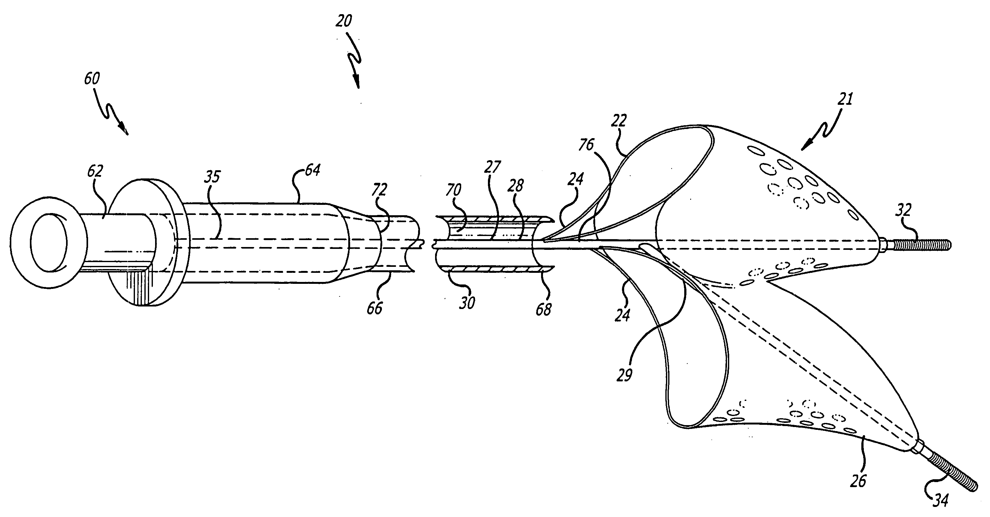
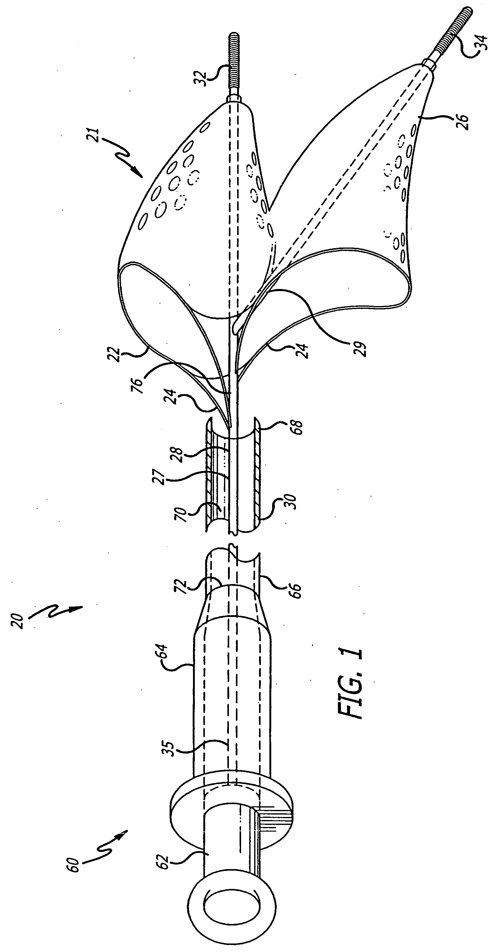
[0021] Turning now to the drawings, in which like reference numerals represent like or corresponding elements in the drawings, FIG. 1 illustrates one particular embodiment of an apparatus 20 for filtering embolic material from a bifurcated vessel incorporating features of the present invention. The apparatus includes an embolic filtering device 21 designed to capture embolic debris which may be created and released into a bifurcated biological vessel during an interventional procedure. The embolic filtering device 21 includes an expandable bifurcated filter assembly 22 having a self-expanding filter support 24 and a bifurcated filter element 26 attached thereto. In this particular embodiment, the expandable filter assembly 22 is mounted onto the distal portion of a bifurcated delivery device 27 including a first elongated (solid or hollow) cylindrical shaft, such as a first guide wire 28, and a second elongated (solid or hollow) cylindrical shaft, such as a second guide wire 29. The...


PUM


Abstract

An embolic filtering device for use in a bifurcated vessel includes delivery device having a first guide wire and a second guide wire. The second guide wire diverges from the distal-end region of the first guide wire. The filter device also includes a filter support having a first deployment member and a second deployment member. These deployment members can be formed as a first loop and a second loop. A bifurcated filter element is coupled to the filter support. The distal-end region of the first guide wire extends through a first leg of the filter element and the second guide wire extends through a second leg of the filter element. During use, the first leg of the filter element is deployed within a first branch of the bifurcated vessel and the second leg of the filter element is deployed within a second branch of the bifurcated vessel.

Description

BACKGROUND OF THE INVENTION [0001] The present invention relates generally to filtering devices used when an interventional procedure is being performed in a stenosed or occluded region of a biological vessel to capture embolic material that may be created and released into the vessel during the procedure. The present invention is more particularly directed to an embolic filtering device for use in a bifurcated vessel, such as, for example, a renal artery or carotid artery. [0002] Numerous procedures have been developed for treating occluded blood vessels to allow blood to flow without obstruction. Such procedures usually involve the percutaneous introduction of an interventional device into the lumen of the artery, usually by a catheter. One widely known and medically accepted procedure is balloon angioplasty in which an inflatable balloon is introduced within the stenosed region of the blood vessel to dilate the occluded vessel. The balloon dilatation catheter is initially inserte...

Claims


Application Information

Patent Timeline
Patent Type & Authority Applications(United States)
IPC IPC(8): A61F2/01A61F2/06
CPCA61F2/013A61F2002/065A61F2230/001A61F2002/018A61F2230/0008A61F2230/008A61F2/012
Inventor DENISON, ANDY E.BOYLE, WILLIAM J.
Owner ABBOTT CARDIOVASCULAR
Why Eureka
Try Eureka