Method and apparatus for determining filtrate contamination from density measurements

a technology of density measurement and method, applied in the field of downhole formation fluid sample analysis, can solve the problem of not being able to collect formation fluid samples

Inactive Publication Date: 2005-08-18
BAKER HUGHES INC
View PDF19 Cites 68 Cited by
  • Summary
  • Abstract
  • Description
  • Claims
  • Application Information

AI Technical Summary

Benefits of technology

[0012] The present invention provides a downhole system, apparatus and method to determine the percentage of oil-based or water-based mud filtrate contamination in a formation fluid sample. The present invention determines the percentage of filtrate contamination in a sample comprised of a mixture of formation fluid (crude oil or brine) and filtrate. The filtrate percentage is determined from a relationship between the densities of the contaminated formation fluid sample, the density of the formation fluid and the density of filtrate. Filtrate is typically oleic (from oil-based mud) or aqueous (from water-based mud). The density of formation fluid is determined from a series of high precision pressure measurements of formation fluid at a plurality of depths in a hydrocarbon producing well. The present invention provides a function that performs a least squares fit of the pressure to depth relationship. It is well known that pressure, P=ρgh, thus, the best-fit slope is the density ρ, times the acceleration of gravity, g. The present invention additionally provides a method and apparatus for determining sample cleanup from a leveling off in the reduction of the percentage of filtrate contamination in a fluid removed from a formation during continuous pumping.

Problems solved by technology

If it is known that there is too much filtrate contamination in the sample (more than about 5 or 10%), it is seldom feasible to collect the formation fluid sample in a sample tank until the contamination level drops to an acceptable level.

Method used


Image

  • Method and apparatus for determining filtrate contamination from density measurements
  • Method and apparatus for determining filtrate contamination from density measurements
  • Method and apparatus for determining filtrate contamination from density measurements

Examples


Embodiment Construction

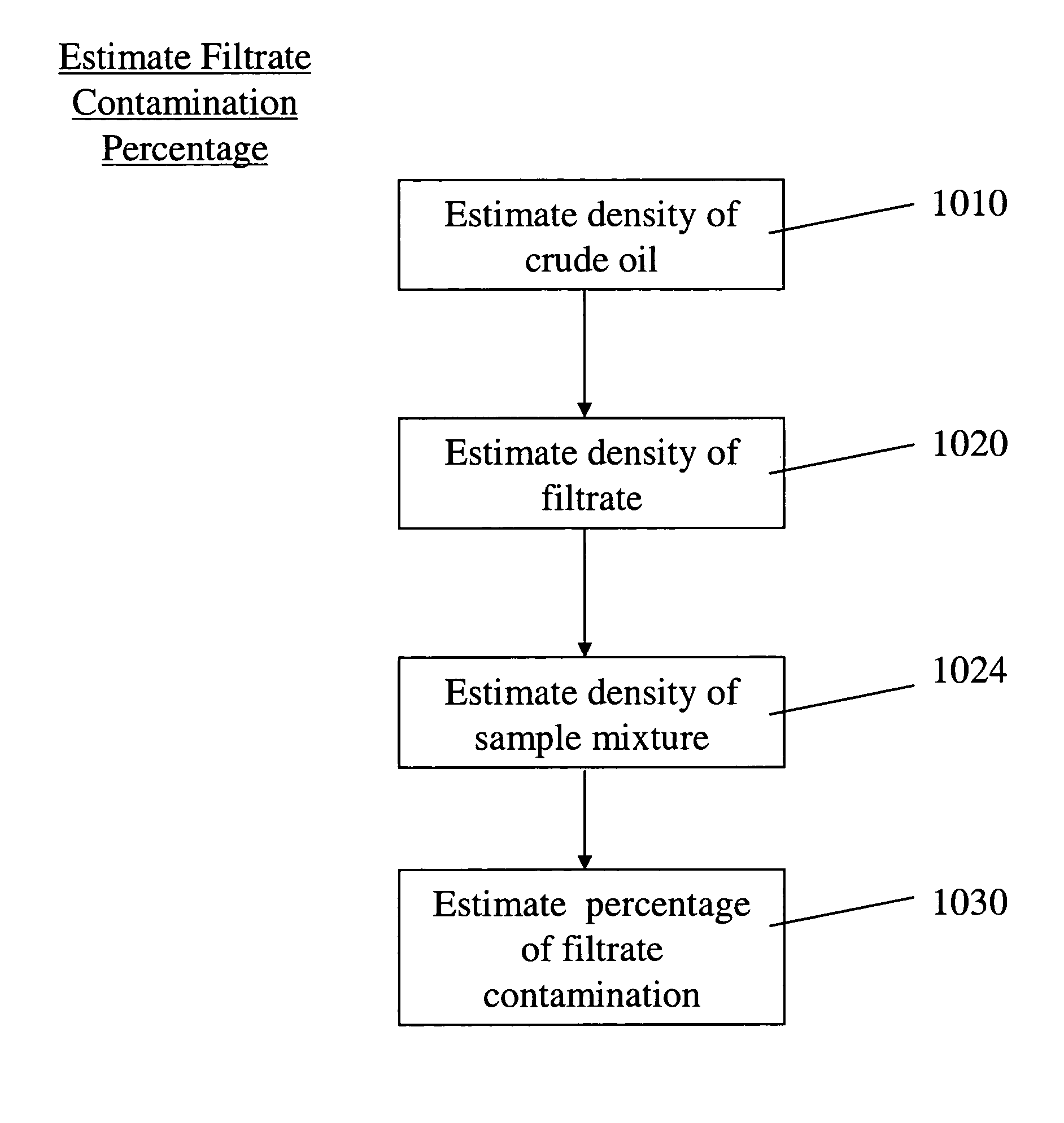
[0034] The present invention provides a downhole method and apparatus to determine the percentage of mud filtrate contamination in a formation fluid sample. The present invention determines the percentage of filtrate contamination in a sample comprised of a mixture of crude oil and oil based mud filtrate or of formation brine and water based mud filtrate. The filtrate contamination percentage is determined from a relationship between the density of the filtrate-contaminated sample, the density of the pure formation fluid, and the density of the filtrate.

[0035] The density of formation fluid is determined from a series of high precision pressure measurements of formation fluid at a plurality of depths in a hydrocarbon producing well. The present invention provides a function that performs a least squares fit of the pressure to depth. As is well known, P=ρgh, thus the best-fit slope is the density ρ, times the acceleration of gravity, g. The present invention additionally provides a ...


PUM

PropertyMeasurementUnit
frequency responseaaaaaaaaaa
densityaaaaaaaaaa
pressureaaaaaaaaaa

Abstract

The present invention provides a downhole method and apparatus to determine the percentage of oil based mud or water based mud filtrate contamination in a formation fluid sample. The present invention determines the percentage of filtrate contamination in a sample comprised of a mixture of crude oil and an oil based mud filtrate or of formation brine and a water based mud filtrate. The filtrate contamination percentage is determined from a relationship between the densities of uncontaminated formation fluid and filtrate. Filtrate may oil based or water based mud. The density of formation fluid is determined from a series of high precision pressure measurements of formation fluid at a plurality of depths in a hydrocarbon producing well. The density of filtrate is provided by downhole measurements with a flexural mechanical resonator or by measurements made downhole or at the surface.

Description

CROSS REFERENCE TO RELATED PATENT APPLICATIONS [0001] This patent application claims priority from United States Provisional patent application Ser. No. 60 / 536,371, filed on Jan. 14, 2004 entitled Method and Apparatus for Determining Oil Based Mud Filtrate Contamination from High Precision Density Measurements, by Rocco DiFoggio.BACKGROUND OF THE INVENTION [0002] 1. Field of the Invention [0003] The present invention relates to the field of downhole formation fluid sample analysis in hydrocarbon producing wells. More particularly, the present invention relates to a method and apparatus for determining the percentage of filtrate contamination in a formation fluid sample from a relationship between formation fluid density, filtrate density and sample density. [0004] 2. Background of the Related Art [0005] In wellbore exploration, drilling mud such as oil-based mud and synthetic-based mud types are used. The filtrates from these mud types generally invade the formation through the bore...

Claims


Application Information

Patent Timeline
Patent Type & Authority Applications(United States)
IPC IPC(8): E21B47/10G01N9/00G01N29/02G01N33/28
CPCE21B47/10G01N9/002G01N29/022G01N33/2823G01N2291/014G01N2291/101G01N2291/0256G01N2291/02818G01N2291/0422G01N2291/0426G01N2291/0427G01N2291/0222E21B49/087
Inventor DIFOGGIO, ROCCO
Owner BAKER HUGHES INC
Why Eureka
Try Eureka