
Method of manufacturing container top parts forming container lids

a container lid and container top technology, applied in the field of container lid manufacturing, can solve the problems of warped combined covers and foils in automated manufacturing processes, difficult to establish expensive procedures, and difficult to meet the requirements of container lids, so as to improve the adhesion between the cover and the foil

Inactive Publication Date: 2005-08-25
STEG HENNING
View PDF2 Cites 0 Cited by
  • Summary
  • Abstract
  • Description
  • Claims
  • Application Information

AI Technical Summary

Benefits of technology

[0014] In this way also, the flow behavior of the material which is injected into the injection mold and which forms the container top part or cover is improved, since the foil is no longer a “cold” insulator, but the foil is maintained at a higher temperature range so that the temperature difference between the foil and the plastic material of which the cover consists is not as large as it is in the state of the art methods.
[0015] This measure has additionally the advantage that the connection, that is, the adhesion between the cover and the foils is improved. Upon cooling of the joined cover and foil after manufacture, the cover and the foil connected thereto shrink synchronously with the result that the cover and the foil, after cooling down to ambient temperature, form a planar structure, that is, a planar compound arrangement.
[0021] It is also advantageous if the temperature of a device by which the foil is transferred to the injection mold is maintained at the same temperature which is provided for the foil in the injection mold, for example at a temperature of 65° C. to 80° C. In this way, the foil has reached its desired temperature-dependent expansion when it is placed into injection mold.
[0024] In order to provide for a uniform temperature distribution in the foil for the manufacture of the cover, it is finally advantageous to heat already the storage area for the foils so that during the transfer of the foil for example by the transfer device from the storage location to its position in the injection mold, only so much heat has to be supplied to the foil as is needed to compensate for heat losses during the transfer from the storage area to the position in the injection mold. Then also the heating means in the transfer or handling device may be relatively simple which is equally true for the respective temperature control means.

Problems solved by technology

In addition, the material, of which the foil consists, is often different from the material which forms the cover.
Procedurally, it is very problematic to use such warped combined covers and foils in an automated manufacturing process, that is, to mount them onto a container which is filled with the desired product and to close the container hermetically with such a warped cover in an airtight manner so that it is protected from outer influences.
The covers, which are warped occasionally in several directions can, after their manufacture, that is after having been joined with a foil, be mounted onto a container only with the use of expensive procedural measures for handling such a compound cover.
As a result, expensive procedures must be established in order to position such covers accurately on the container and maintain it in their proper position until the closing procedure is completed.
With presently available methods, this is not guaranteed in a way as it is desirable from manufacturing and hygienic points of view.

Method used


Image

  • Method of manufacturing container top parts forming container lids
  • Method of manufacturing container top parts forming container lids
  • Method of manufacturing container top parts forming container lids

Examples


Embodiment Construction

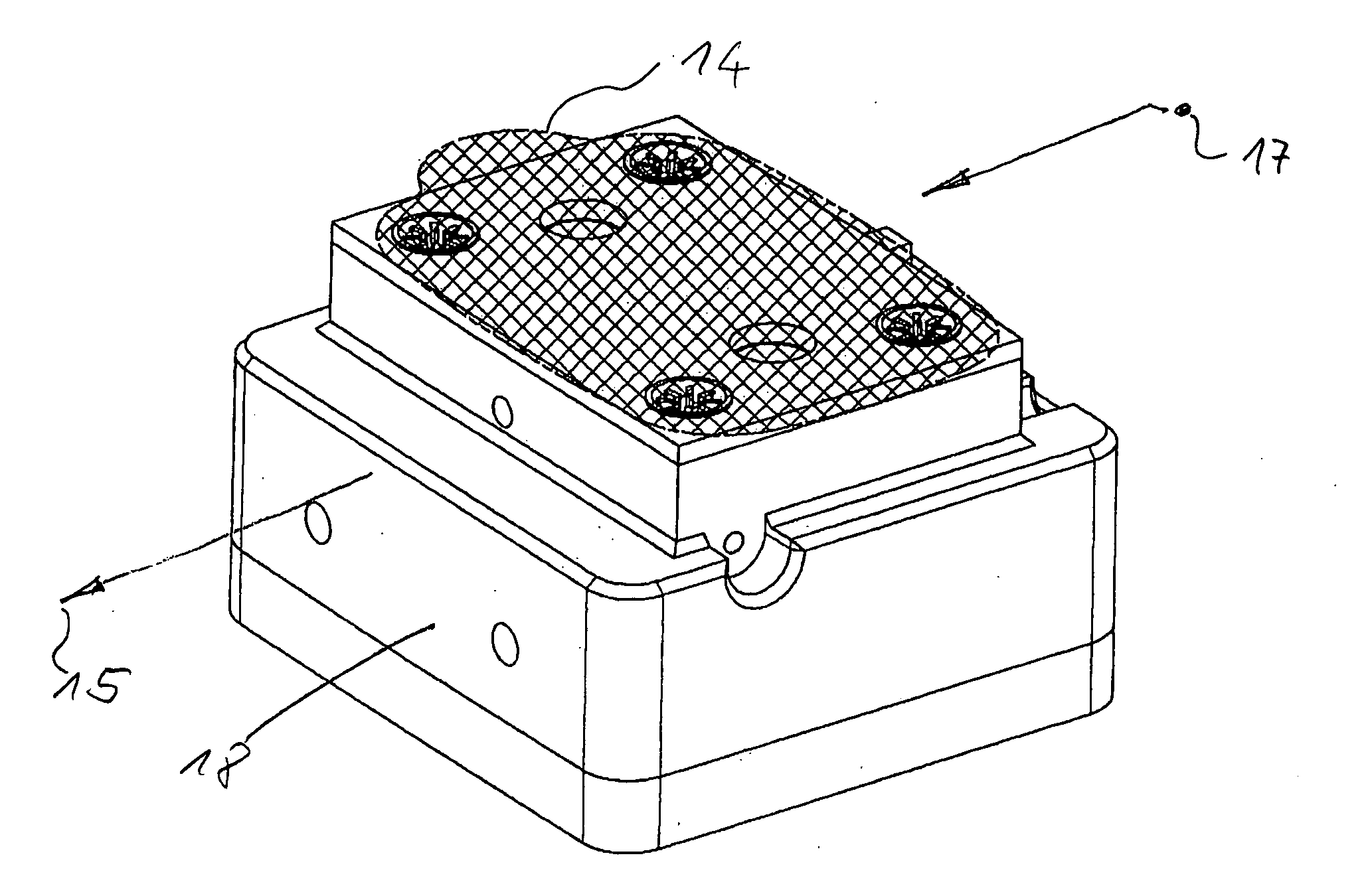
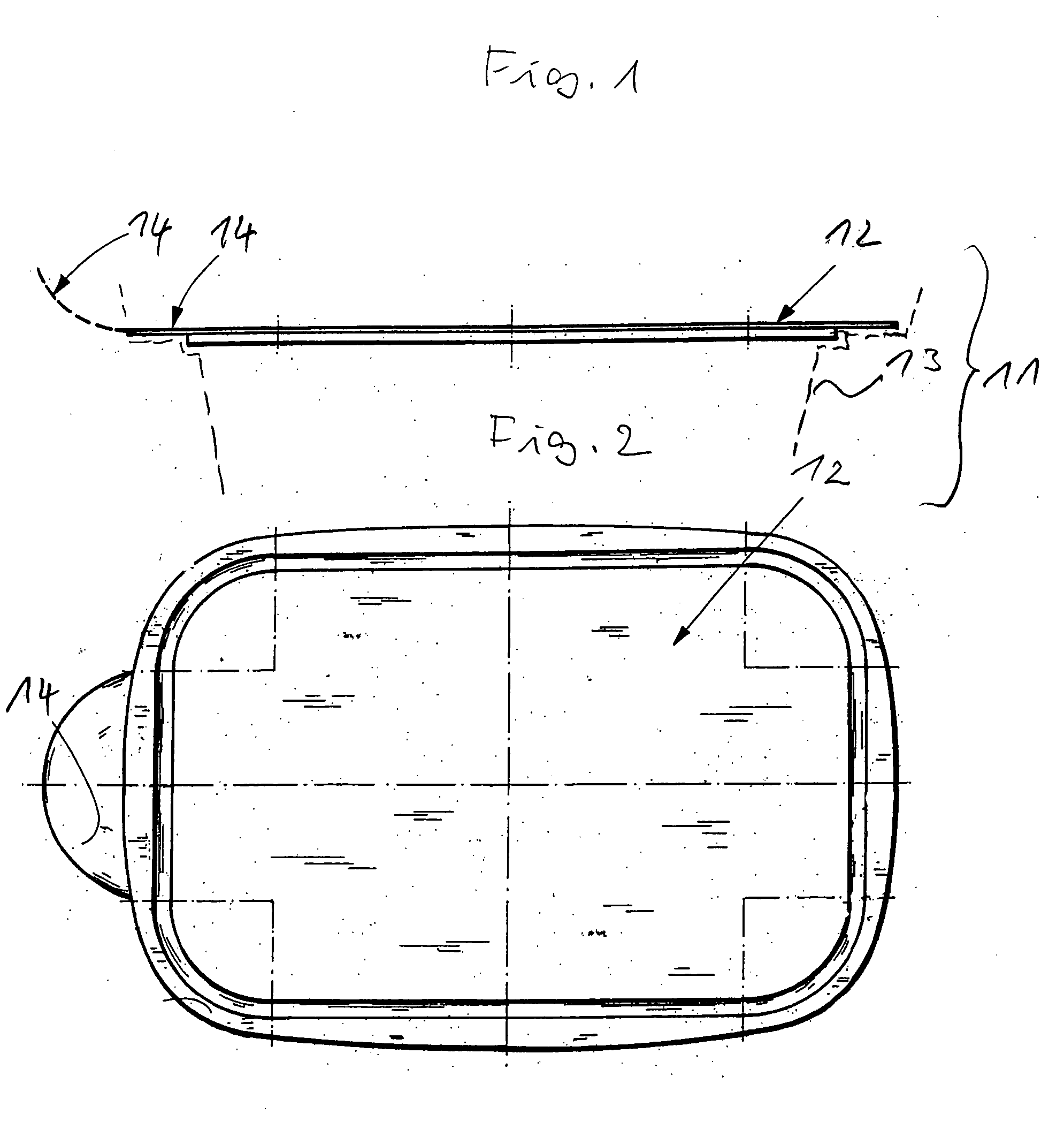
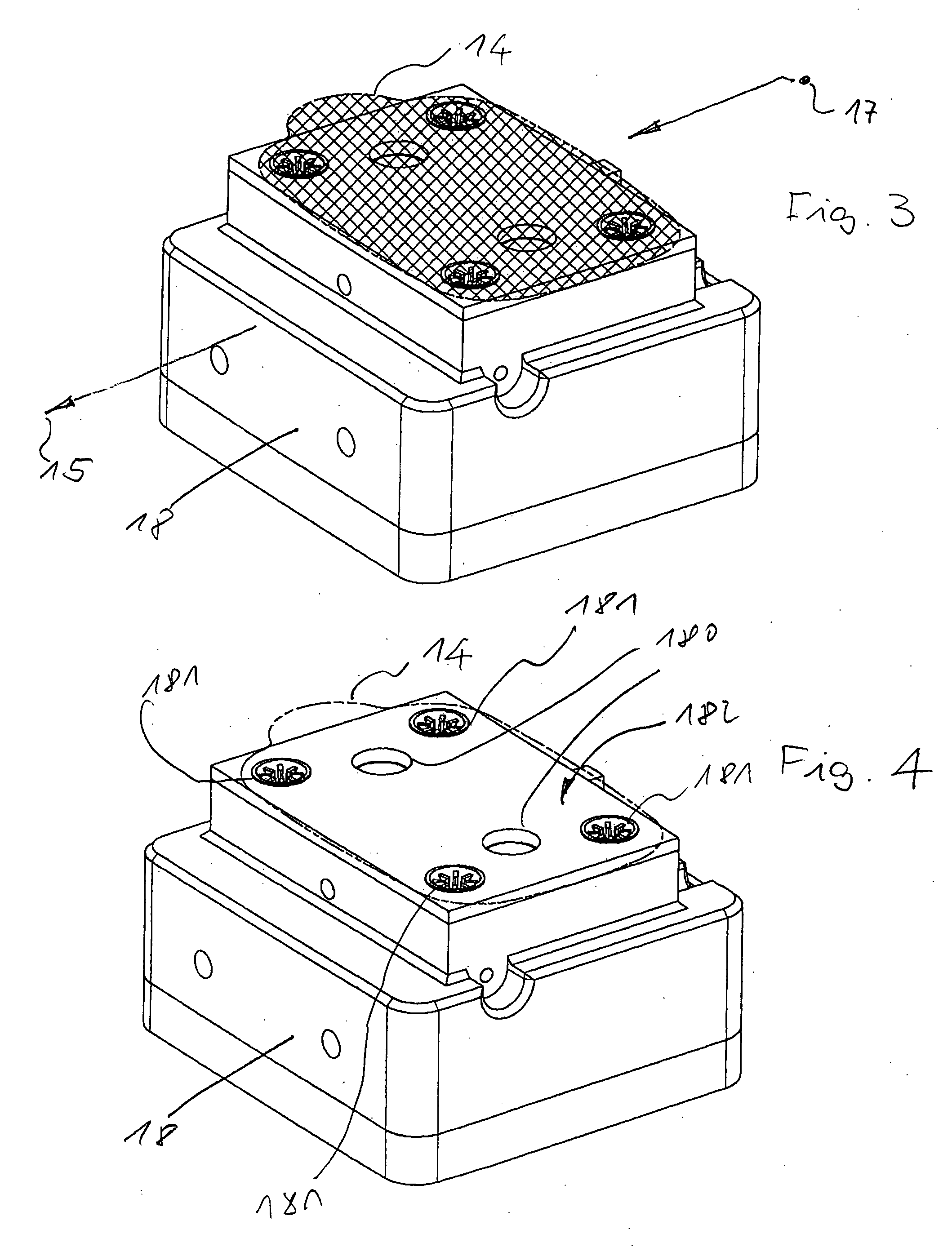
[0036] First, reference is shortly made to the container top part or container cover 12 manufactured by the method according to the invention and shown schematically in FIGS. 1 and 2. The container top part 12 consists of an essentially flat body of an injection-moldable material to which a foil 14 is applied. On the foil 14, optically noticeable instructions may be provided such as images and / or print providing information concerning the content of the container 11, which is closed by a cover 12 according to the invention and which is shown in FIG. 1 only schematically by dashed lines. Generally, the container top part 12 and the foil 14 consist of the same plastic material, for example OF polypropylene. The plastic material forming the container top part 12 and the container bottom part 13 however may also be different.

[0037] Concerning the design of the container 11, that is, the container top part 12 and the container bottom part 13, reference is made to European patent applica...


PUM

PropertyMeasurementUnit
temperatureaaaaaaaaaa

Abstract

In a method for the manufacture of container top parts serving as covers of containers for solid, paste-like as well as flowable or particulate products, particularly for food products, wherein a foil is disposed on and joined to the container top part and wherein at least the container top part consists of a plastic material, the jointure between the container top part and the foil is established by plastic material which forms the container top part while it is plasticized during injection into an injection mold, into which the foil is placed and heated to a predetermined temperature before the plastic material forming the top part is injected into the injection mold and the and the top part and the foil joint therewith are then permitted to jointly cool down.

Description

BACKGROUND OF THE INVENTION [0001] The invention relates to a method of manufacturing container top parts forming container lids of containers for solid, paste-like, flowable, or particulate products, particularly for food products wherein a foil is disposed on the container top part and wherein at least the container top part consists of a plastic material. [0002] In European patent application, 03 010 210.1, a container is described for containing solid, paste-like, as well as flowable and particulate products, particularly food products. This container comprises a lower container part for containing the product and a container top part serving as a container lid. On the container top part, a foil is disposed which is provided with printed or pictorial information concerning the container content and possibly instructions concerning the use of the container content. Such foils which are also called labels are applied to containers particularly to plastic containers of the type des...

Claims


Application Information

Patent Timeline
Patent Type & Authority Applications(United States)
IPC IPC(8): B65D43/04B29C45/14
CPCB29C45/14B29C45/14008B29L2031/565B29C2045/14918B29C2045/14877
Inventor STEG, HENNING
Owner STEG HENNING
Learn More