Exposure apparatus, optical projection apparatus and a method for adjusting the optical projection apparatus

a technology of optical projection apparatus and exposure apparatus, which is applied in the field of scanning projection exposure apparatus, can solve the problems of increased production cost of the apparatus, increased magnification error of the projection optical system, and increased accuracy, and achieve excellent imaging performance, without lowering throughput

Inactive Publication Date: 2005-08-25
NIKON CORP
View PDF96 Cites 2 Cited by
  • Summary
  • Abstract
  • Description
  • Claims
  • Application Information

AI Technical Summary

Benefits of technology

[0013] The present invention has been accomplished taking the above problems into consideration and an object of the present invention is to provide an exposure apparatus which can realize full scanning exposure of a large exposure area with excellent imaging performance and without lowering the throughput.
[0018] Also, since each projection optical system is compact, scanning exposure can be made while minimizing occurrence of aberrations and keeping excellent imaging performance.

Problems solved by technology

Because of this requirement, the method had such disadvantages that the magnification error of projection optical system must be decreased as close to 0 as possible, that the alignment accuracy must be greatly improved, and that the production cost of the apparatus is increased.
In order to increase the scale of projection optical system, however, large-scale optical, elements must be produced with very high accuracy, which results in increasing the production cost and the size of apparatus.
Also, there was a disadvantage that the size increase of projection optical system caused an increase in aberrations or a decrease in imaging performance.

Method used


Image

  • Exposure apparatus, optical projection apparatus and a method for adjusting the optical projection apparatus
  • Exposure apparatus, optical projection apparatus and a method for adjusting the optical projection apparatus
  • Exposure apparatus, optical projection apparatus and a method for adjusting the optical projection apparatus

Examples


second embodiment

[0178] the present invention is next described referring to the accompanying drawings.

[0179]FIG. 18 is a perspective view to show the structure of an exposure apparatus according to the second embodiment of the present invention. Also, FIG. 19 is a drawing to show the structure of projection optical systems in the exposure apparatus of FIG. 18.

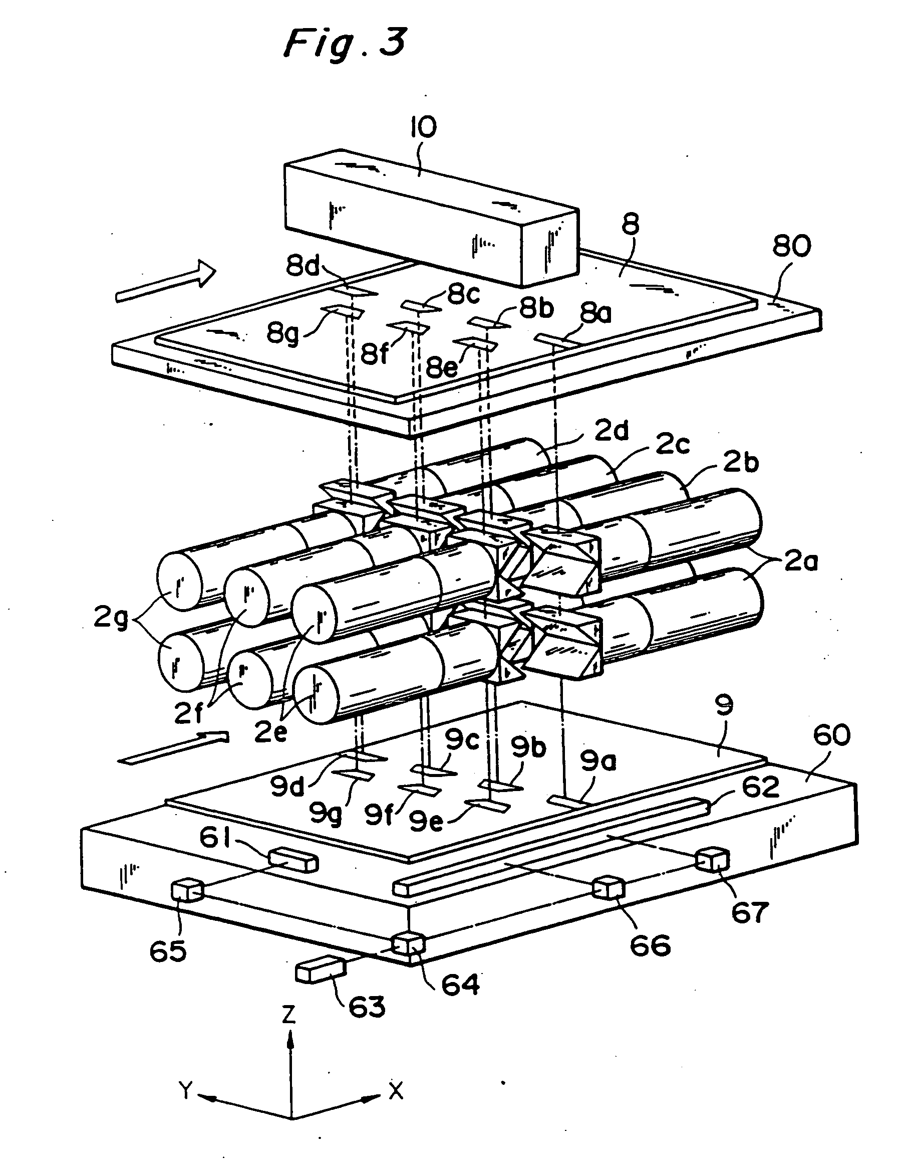
[0180] The second embodiment Is different from the embodiment as shown in FIG. 3 in that the structure of projection optical systems 302a-302g is different from that in the first embodiment as detailed below and in that because of it the shape of field regions 308a-308g and exposure regions 309a-309g is substantially of a semi-circular ring. The second shown in FIG. 18 is the same as the first embodiment shown in FIG. 3 except for the above points.

[0181]FIG. 19 is a drawing to schematically show the structure of each projection optical system. A projection optical system as shown is composed of a first partial optical system 321-323, a field...

first embodiment

[0222] Accordingly, as explained in the first embodiment, an image formed on the plate 9 is a real size erect image of a circuit pattern on the mask 8, a scanning exposure can be performed by moving integrally the both of the mask 8 and the plate 9.

[0223] In addition, since the plane reflective surface M1 is located at the rear focal-point position of the refractive optical system G1, the first partial optical system K1 as described above is telecentric on the side of mask 8 and on the side of field stop FS. Further, since the plane reflective mirror M2 is located at the rear focal-point position of the refractive optical system G2, the second partial optical system K2 is also telecentric on the side of field stop FS and the side of plate 9. Accordingly, the first projection optical system 535a is a both side (mask 8 side and plate 9 side) telecentric optical system.

[0224] Next, the exposure area of the first projection optical system 535a in FIG. 27 is described referring to FIGS....

fifth embodiment

[0232] Next the fifth embodiment is shown in FIG. 30.

[0233] Only the first projection optical system in the projection optical system is shown also in FIG. 30.

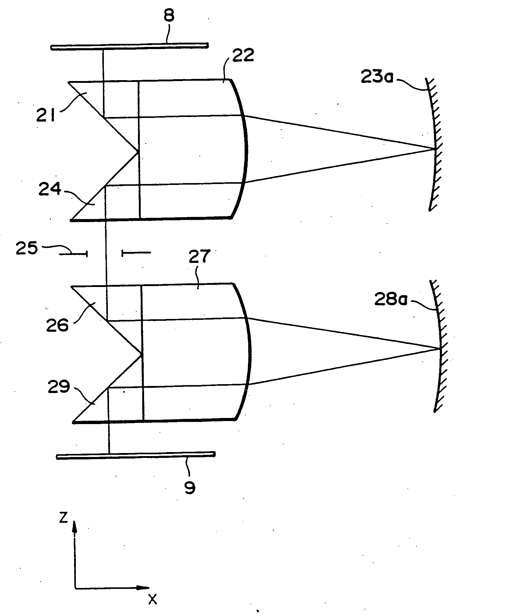
[0234] As shown in FIG. 30, the first projection optical system has a reflective surface 512 inclined at 45° to the surface of mask 8 (XY plane), a refractive optical system 536 of a positive refractive power as a whole, a plane reflective mirror 538 disposed at the rear focal-point position of the refractive optical system, and a reflective member 513 having the roof reflective surfaces. Since the refractive optical system 536 is the same as the refractive optical system of the forth embodiment shown in FIG. 29 is omitted herein.

[0235] The reflective member 513 has two reflective surfaces (roof reflective surfaces) 513a, 513b perpendicular to each other, for example as shown in FIG. 31. Here, a ridgeline 513c of the two reflective surfaces 513a, 513b has an inclination of 45° relative to the XY plane.

[0236] Returning to FI...


PUM

PropertyMeasurementUnit
angleaaaaaaaaaa
optical systemaaaaaaaaaa
opticalaaaaaaaaaa

Abstract

An exposure apparatus includes a plurality of projection optical systems and a substrate stage. Each of the plurality of projection optical systems forms an exposure field on the substrate. The substrate stage holds the substrate and moves in at least a scanning direction extending in a straight line. The plurality of exposure fields are arranged along a direction crossing the scanning direction. The plurality of projection optical systems and the substrate relatively move during an exposure field forming operation along the scanning direction.

Description

RELATED APPLICATIONS [0001] This is a Continuation-In-Part application of application Ser. No. 08 / 259,771 filed on Jun. 14, 1994, now pending.BACKGROUND OF THE INVENTION [0002] 1. Field of the Invention [0003] The present invention relates to an exposure apparatus, and more particularly to a scanning projection exposure apparatus which performs exposure while moving a first object and a second object. [0004] 2. Related Background Art [0005] Liquid crystal display panels are frequently used these days as a display device for word processors, personal computers, televisions, etc. A liquid crystal display panel is fabricated by patterning of transparent thin-film electrodes in a desired shape on a glass substrate by the photolithography technique. As an apparatus for the lithography a mirror projection type aligner is used for exposure-printing an original pattern formed on a mask onto a photoresist layer on a glass substrate through a projection optical system. [0006]FIG. 1 and FIG. 2...

Claims


Application Information

Patent Timeline
Patent Type & Authority Applications(United States)
IPC IPC(8): G02B13/22G02B17/00G02B17/06G02B17/08G02B27/10G03F7/20
CPCG03F7/70358G03F7/70275G02B13/22G02B17/002G02B17/008G02B17/045G02B17/0605G02B17/08G02B17/0812G02B17/082G02B17/0828G02B17/086G02B17/0892G02B27/144G02B27/145G03B27/32G03F7/70066G03F7/70216G03F7/70225G03F7/70241G03F7/70791
Inventor TANAKA, MASASHIKATO, MASAKI
Owner NIKON CORP
Why Eureka
Try Eureka