Optical device and projector
- Summary
- Abstract
- Description
- Claims
- Application Information
AI Technical Summary
Benefits of technology
Problems solved by technology
Method used
Image
Examples
1st embodiment
[0060] Now, a first embodiment of the present invention will be described below by referring to the accompanying drawings.
[0061] [Configuration of Projector]
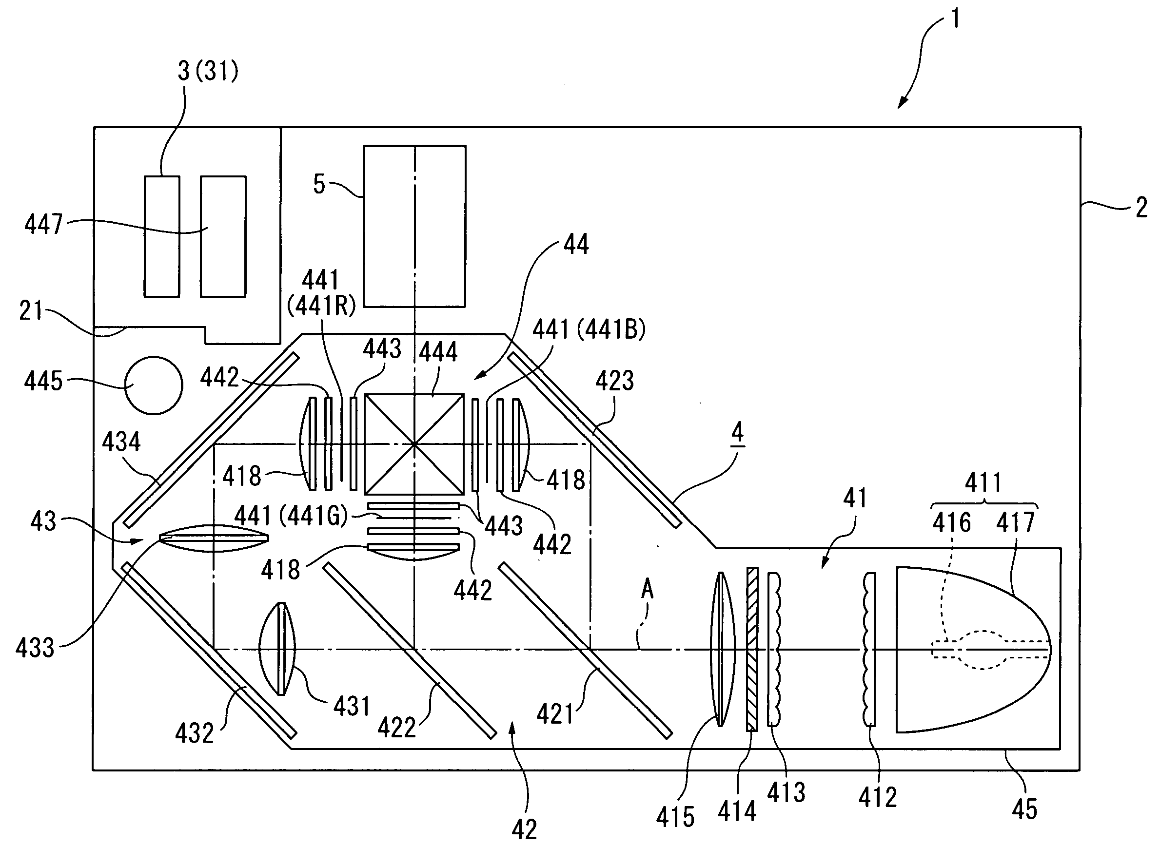
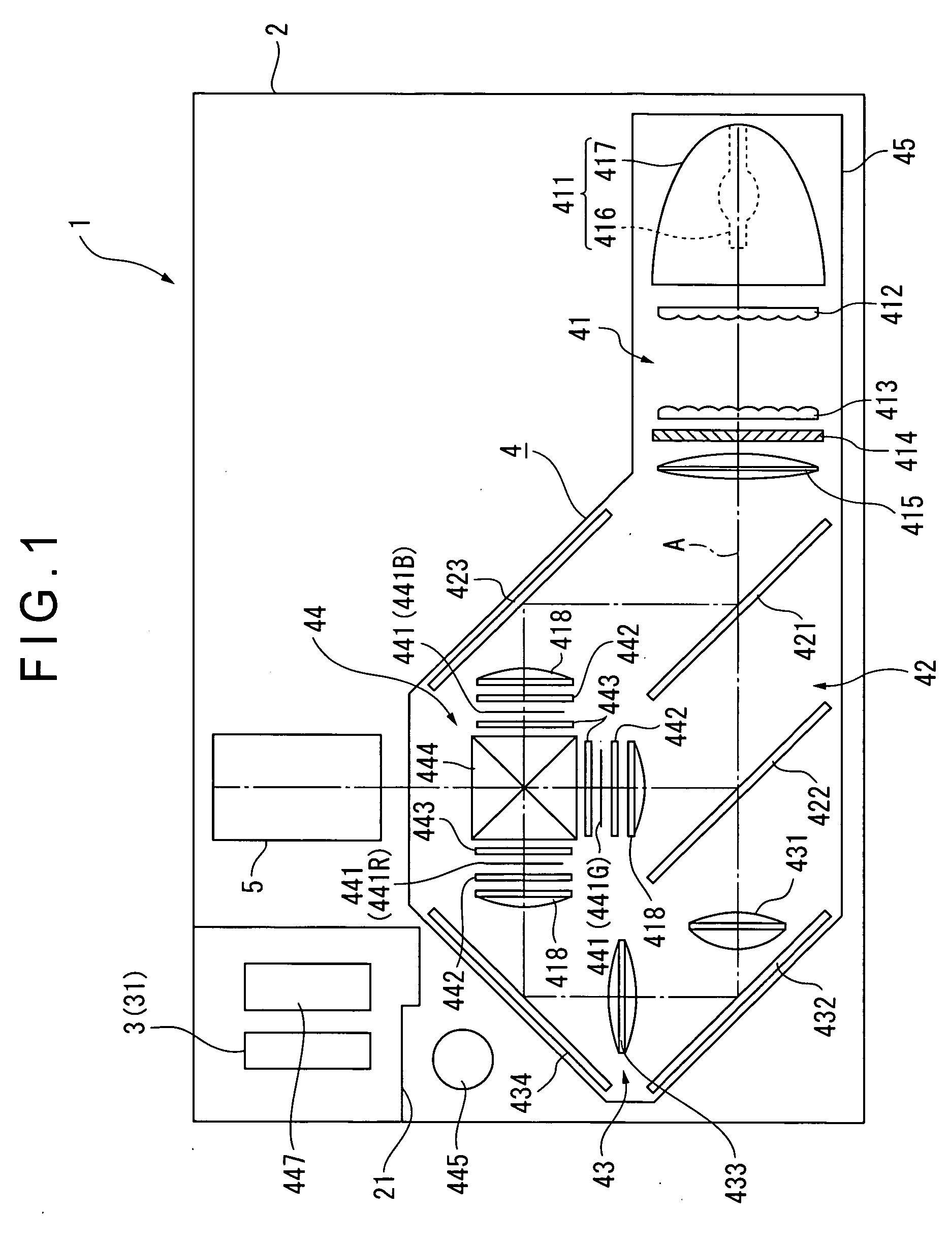
[0062]FIG. 1 is a schematic illustration of a projector 1, showing the configuration thereof.
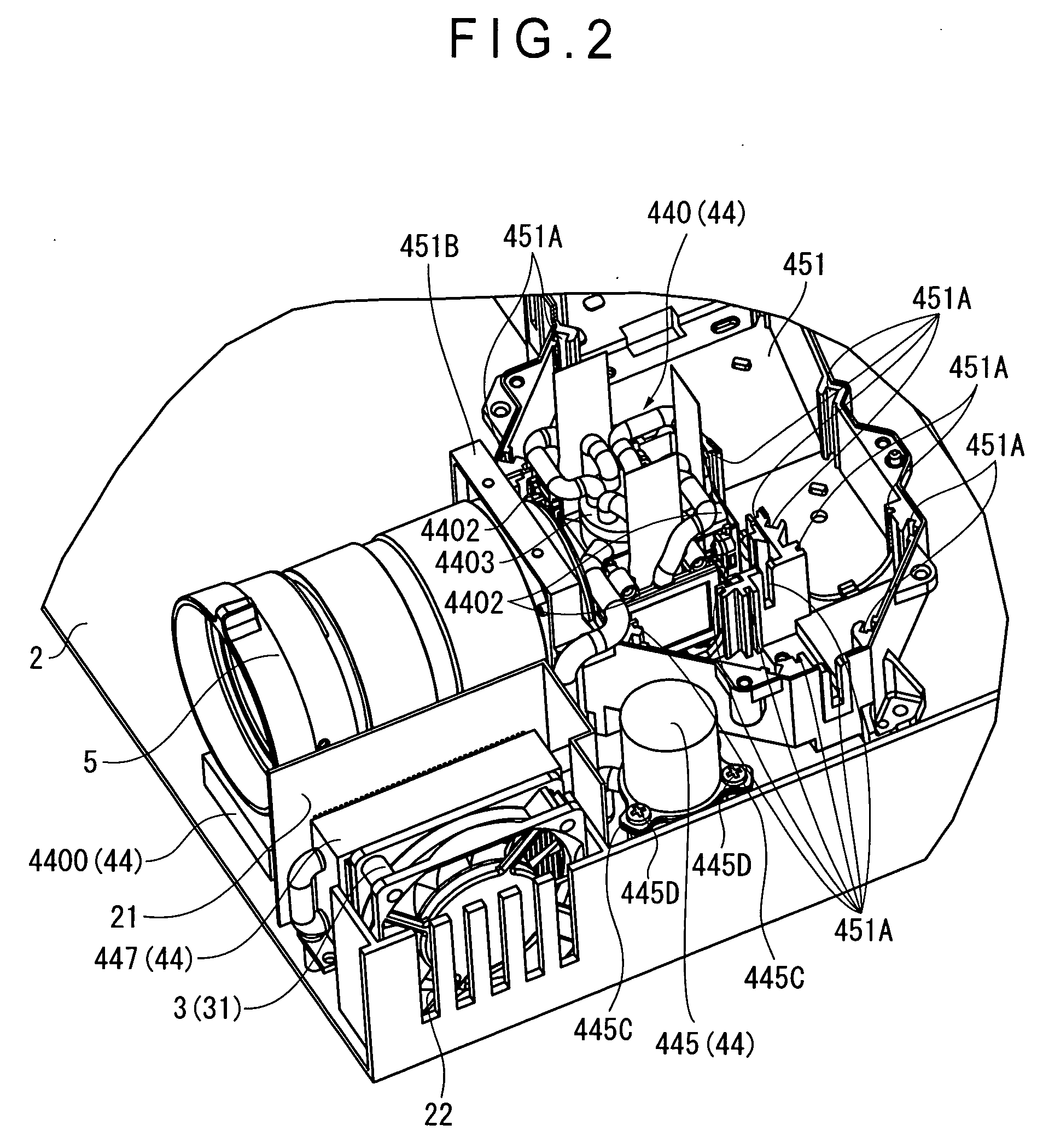
[0063] The projector 1 forms an optical image by modulating the light beam emitted from a light source and enlarging and projecting the formed optical image onto a screen. The projector 1 includes a exterior case 2, a cooling unit 3, an optical unit 4 and a projection lens 5 that is an optical projection device.
[0064] Note that, although not shown, a power source block, a lamp drive circuit and other components are arranged in the space not occupied by the cooling unit 3, the optical unit 4 and the projection lens 5.
[0065] The exterior case 2 is typically made of synthetic resin and has a substantially cubic profile so as to contain the cooling unit 3, the optical unit 4 and the projection lens 5 in the in side. Although not shown, t...
2nd embodiment
[0210] Now, the second embodiment of the present invention will be described by referring to the related drawings.
[0211] In the following description, the structures and the components same as or similar to those of the first embodiment will be denoted respectively by the same reference symbols and will be summarized or not be described any further.
[0212] In optical device 44 of the above-described first embodiment, the optical device main body 440 can be removably fitted to the main tank 445 and the radiator 447 by means of two fluid circulating member link sections 446.
[0213] On the other hand, in an optical device 54 of the second embodiment, the main tank 545 is fitted to the fluid branching section 5401 and integrated to an optical device main body 540. Then, the optical device main body 540 is removably fitted to the radiator 447 by means of the two fluid circulating member link sections 446.
[0214]FIG. 13 is a plan view of the optical device 54 of the second embodiment see...
PUM
 Abstract
Description
Claims
Application Information
 - R&D
- Intellectual Property
- Life Sciences
- Materials
- Tech Scout
- Unparalleled Data Quality
- Higher Quality Content
- 60% Fewer Hallucinations
Browse by: Latest US Patents, China's latest patents, Technical Efficacy Thesaurus, Application Domain, Technology Topic, Popular Technical Reports.
© 2025 PatSnap. All rights reserved.Legal|Privacy policy|Modern Slavery Act Transparency Statement|Sitemap|About US| Contact US: help@patsnap.com


