Image-processing method, image-processing apparatus and image-recording apparatus

a technology of image processing and image recording, applied in the field of image processing method, image processing apparatus and image recording apparatus, can solve the problems of image giving a sense of incompatibility to the viewer, image will collapse, and information on gradation prior to compression or information prior to clipping is lost immediately, so as to reduce the deterioration of image quality and improve the working efficiency of image editing operation

Inactive Publication Date: 2005-08-25
KONICA MINOLTA PHOTO IMAGING
View PDF5 Cites 52 Cited by
  • Summary
  • Abstract
  • Description
  • Claims
  • Application Information

AI Technical Summary

Benefits of technology

[0020] To overcome the abovementioned drawbacks in conventional image-processing method and apparatus, it is an object of the present invention to suppress the deterioration of the image quality due to the image editing operation and to improve the working efficiency of the image editing operation performed by the user, when information of the color gamut and the luminance range are compressed to output-referred image data optimized for the assumed visual image to record the output-referred image data.

Problems solved by technology

This causes the gradation outside the color gamut to be collapsed, and the image will give a sense of incompatibility to the viewer.
However, when compression has been carried out for the color gamut and luminance range as described above, information on gradation prior to compression or information prior to clipping are lost immediately due to the principle of the digital image to be recorded in terms of the discrete value.
This imposes a big restriction on the general versatility of high-quality digital image.
For the image recorded in the sRGB standard color space, however, the information on gradation in the area compressed at a time of recording are lost.
So the smoothness of gradation is deteriorated as compared to the case where the information captured by the photographing device is mapped directly in the area for color reproduction of the printing device.
Further, if gradation compression conditions are not adequate at a time of recording, and there are problems such as a whitish picture, dark face, deformed shadow and conspicuous white skipping in the highlighted area, improvement is very inadequate as compared to the case where the new image is created again from the information gained by the photographing device, even if the gradation setting is changed to improve the image.
This is because information on gradation prior to compression, and information on the portion subjected to deformation or white skipping have been already lost.
The problems introduced above are caused by the procedure where the information on the wide color gamut and luminance range acquired by a photographing device are recorded after having being compressed into the output-referred image data in the state optimized by assuming an image to be viewed.
However, since the sight sensitivity of the viewer varies corresponding to the viewing environment (including luminance and chromaticity of surround light, background, etc.), in which the viewer observes a printed image or a displayed image, aroused is a problem that the “color appearance” actually sensed by the viewer also varies with the variations of the viewing environment.
Therefore, there has been a problem that the “color appearance” of the printed image does not coincide with that of the image displayed on the CRT.
In spite of such the situation, there has been a problem that the deterioration of the image quality and the improvement of working efficiency are not at all considered for the conventional color appearance model.
When considering the current situation, despite that the information amount and the workability retained by the captured image data are severely limited due to the restrictions caused by the device characteristics, it is still difficult to say that the suppression of the image deterioration and the improvement of working efficiency are sufficient.
From now on, aroused is a fear that the deterioration of the image quality and the difficulty of the workability will increase according as the information amount to be retained by the captured image data is getting large.

Method used


Image

  • Image-processing method, image-processing apparatus and image-recording apparatus
  • Image-processing method, image-processing apparatus and image-recording apparatus
  • Image-processing method, image-processing apparatus and image-recording apparatus

Examples


first embodiment

[0354] Referring to FIG. 5 and FIG. 6, the first embodiment of the present invention will be detailed in the following. Initially, the configuration of the first embodiment will be described.
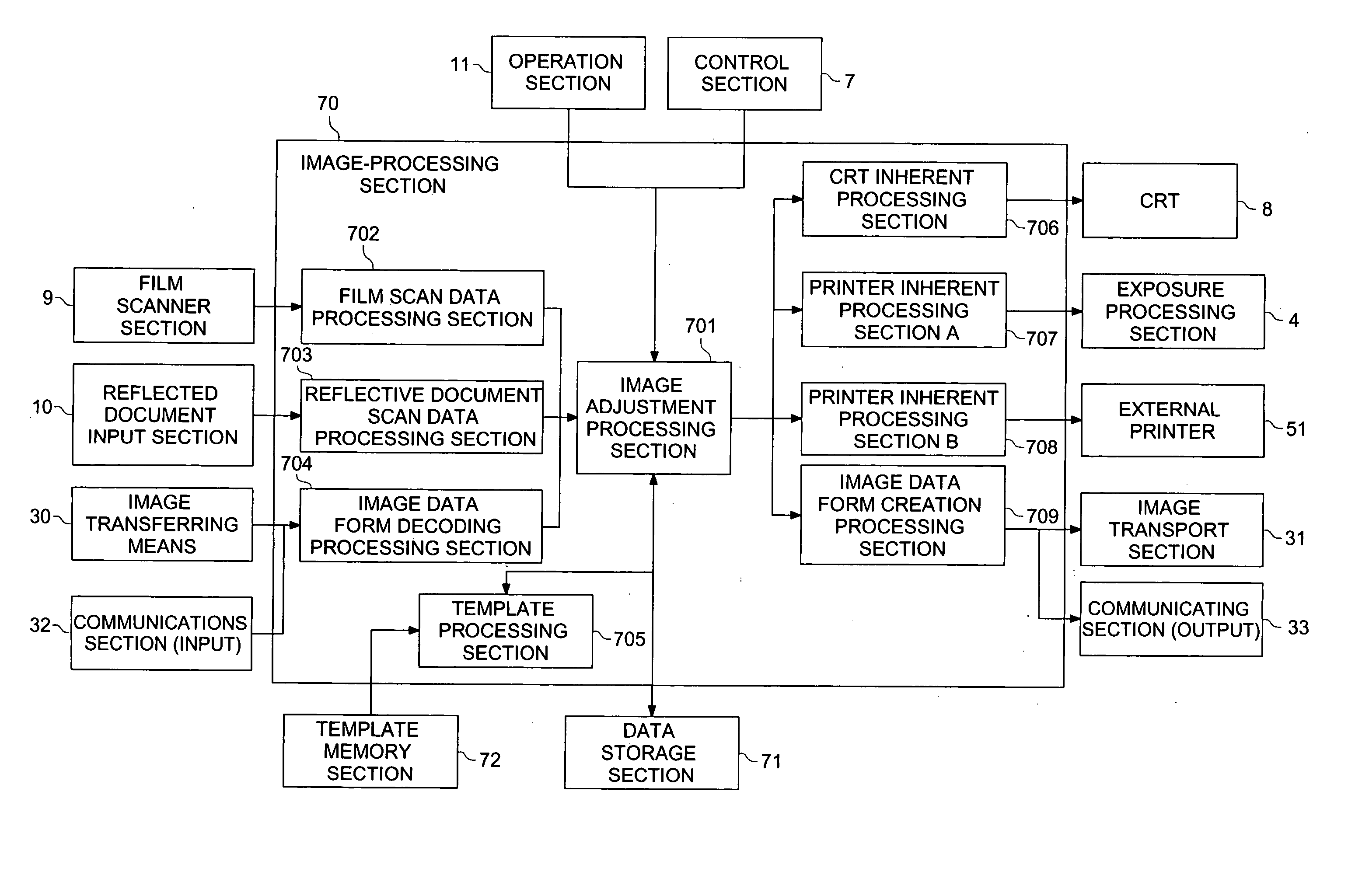
70>

[0355]FIG. 5 shows a block diagram of the internal configuration of image processing section 70. As shown in FIG. 5, image processing section 70 is provided with image adjustment processing section 701, film scan data processing section 702, reflective document scan data processing section 703, image data form decoding processing section 704, template processing section 705, CRT inherent processing section 706, printer inherent processing section A 707, printer inherent processing section B 708, image data form creation processing section 709.

[0356] The film scan data processing section 702 applies various kinds of processing operations to the image data inputted from film scanner section 9, such as a calibrating operation inherent to film scanner section 9, a negative-to-positive reversal ...

second embodiment

[0374] Referring to FIG. 7 through FIG. 13, the second embodiment will be detailed in the following. Initially, the configuration of the second embodiment will be detailed. Since the internal configuration of image-processing section 70 in the second embodiment is the same as that in the first embodiment as shown in FIG. 5, its drawing is omitted and the same reference number will be employed for the same section. In the following description, among the sections included in the second embodiment, only sections different from those in the first embodiment will be detailed.

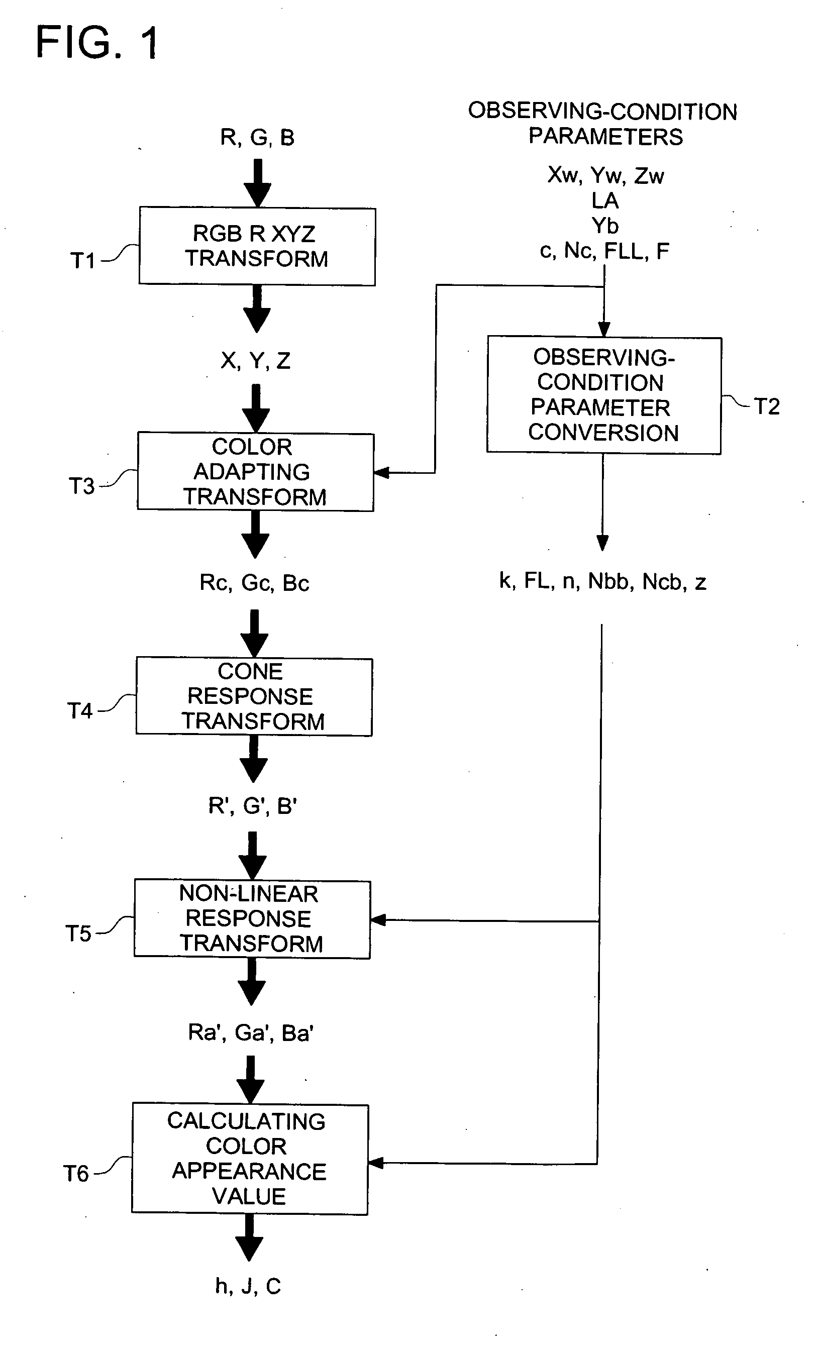
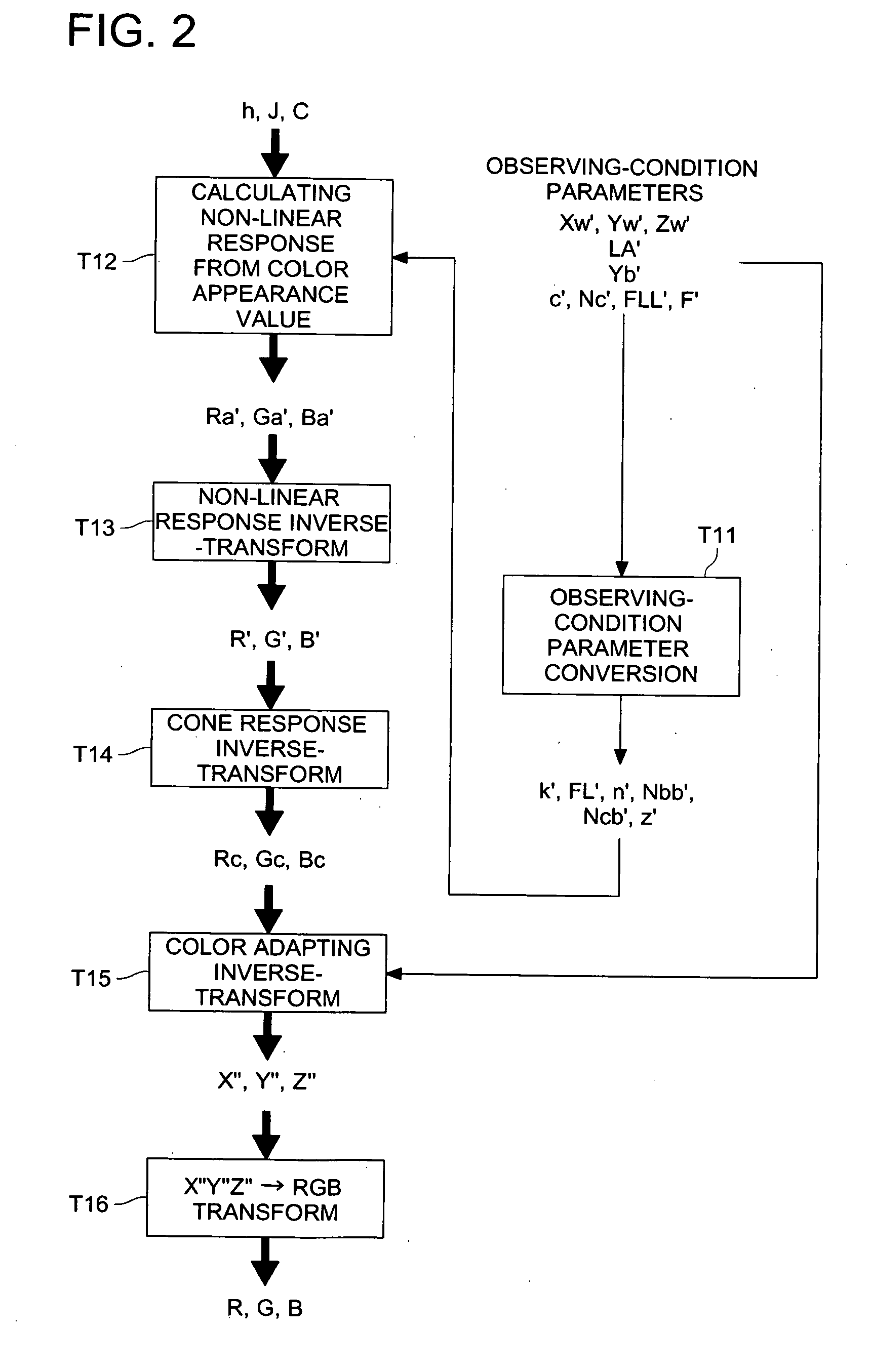
[0375] The image adjustment processing section 701 applies the gradation mapping (refer to the gradation conversion processing shown in FIG. 10) to the inputted captured-image data, and then, converts the gradation mapped image data by employing the color appearance model, in order to implement the color gamut adjustment processing for conducting the color gamut mapping for every outputting medium. According to the...

third embodiment

[0434] Referring to FIG. 14, the third embodiment will be detailed in the following. Initially, the configuration of the third embodiment will be detailed. Since the internal configuration of image-processing section 70 in the third embodiment is the same as that in the first embodiment as shown in FIG. 5, its drawing is omitted and the same reference number will be employed for the same section. In the following description, among the sections included in the third embodiment, only sections different from those in the first embodiment will be detailed.

[0435] Image adjustment processing section 701 converts the color space of the inputted captured-image data to the luminance expansion color space to apply the gradation mapping (the gradation conversion processing shown in FIG. 10). Further, image adjustment processing section 701 converts the gradation mapped image data by employing the color appearance model, in order to implement the color gamut adjustment processing for conducti...


PUM


Abstract

An image processing method of producing visual image-referred data by conducting an image processing to optimize for viewing the visual on an output medium by utilizing a color appearance model, comprises an inputting process to input a user's editing instruction; a reading process to read scene-referred raw data for each editing instruction of an user inputted in the inputting process; and a gamut adjusting process to conduct a gamut mapping for each output medium by converting the read scene-referred raw data in accordance with the user's editing instruction by utilizing a color appearance model.

Description

BACKGROUND OF THE INVENTION [0001] The present invention relates to image-processing methods and apparatus for applying an optimization processing to captured image data so as to optimize a visual image on an outputting medium, and relates to image-recording apparatus for forming the visual image on the outputting medium. [0002] In recent years, the digital image data acquired by scanning a color photo-film or the digital image data captured by an image-capturing apparatus, such as a digital camera, etc., is distributed through such a memory device as a CD-R (Compact Disk Recordable), a floppy disk (registered trade name) and a memory card or the Internet, and is displayed on such a display monitor as a CRT (Cathode Ray Tube), a liquid crystal display and a plasma display or a small-sized liquid crystal monitor display device of a cellular phone, or is printed out as a hard copy image using such an output device as a digital printer, an inkjet printer and a thermal printer. In this ...

Claims


Application Information

Patent Timeline
Patent Type & Authority Applications(United States)
IPC IPC(8): G06T5/00H04N1/407G06T1/00H04N1/46H04N1/60
CPCH04N1/4072H04N1/6011H04N1/6097H04N1/6088H04N1/6058
Inventor TAKANO, HIROAKIITO, TSUKASAMINAKUTI, JUNNAKAJIMA, TAKESHI
Owner KONICA MINOLTA PHOTO IMAGING
Why Eureka
Try Eureka