
Electric/magnetic field analysis method using finite difference time domain, material descriptive method in electric/magnetic analysis, electric/magnetic analysis device, analysis data generation device and storage medium

a technology of electric/magnetic field and time domain, which is applied in the direction of mechanical measurement arrangement, mechanical roughness/irregularity measurement, instruments, etc., can solve the problems of reducing the accuracy of analysis, the shape of the boundary degrades the analysis accuracy, and the calculation cost, etc., to achieve accurate analysis, simplify calculation methods, and accurate conduct

Inactive Publication Date: 2005-08-25
FUJITSU LTD
View PDF3 Cites 2 Cited by
  • Summary
  • Abstract
  • Description
  • Claims
  • Application Information

AI Technical Summary

Benefits of technology

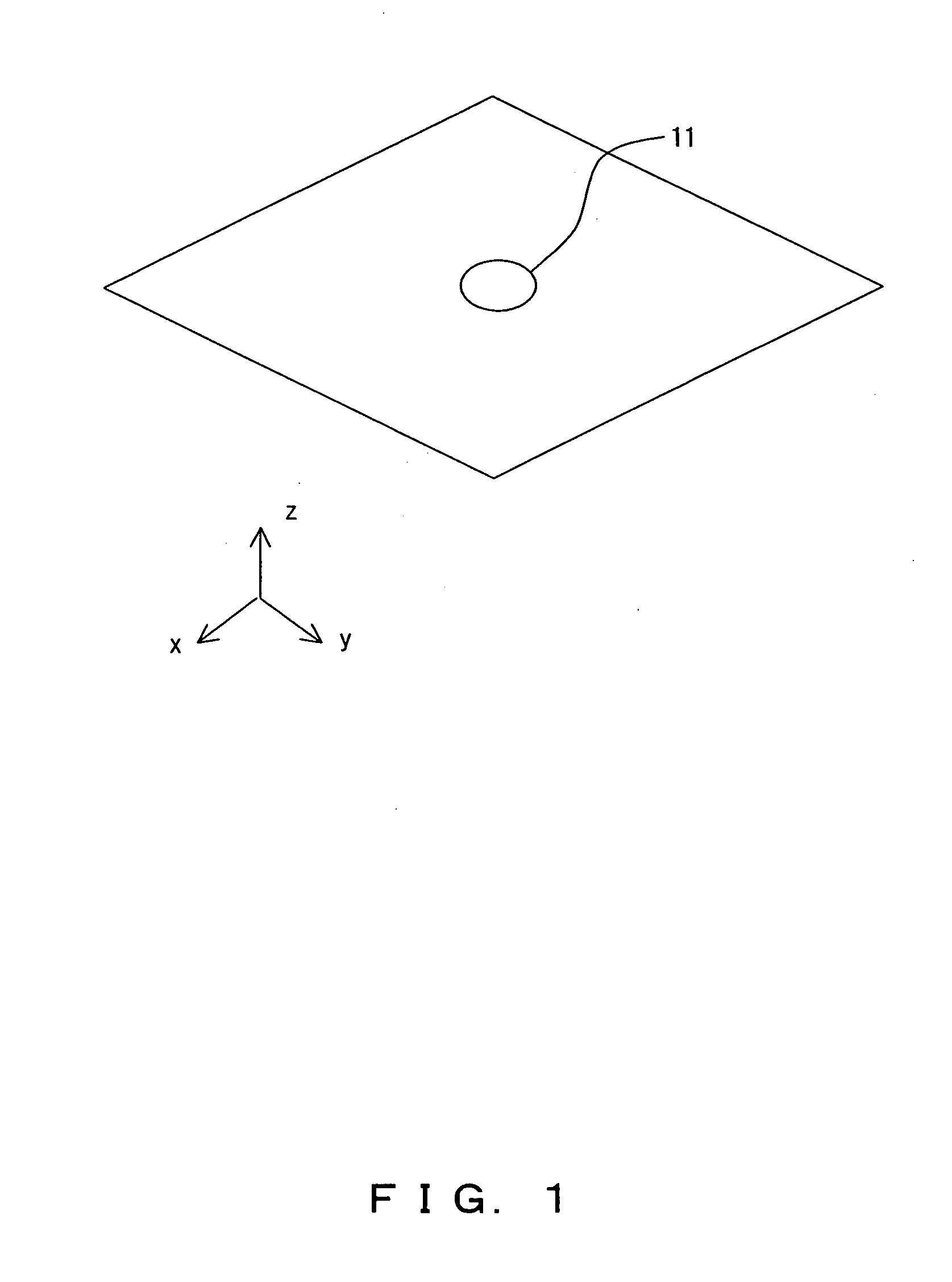
[0009] It is an object of the present invention to provide a general technology for conducting an electric / magnetic field analysis with higher accuracy while suppressing calculation cost, by more accurately expressing the shape (boundary) of an analysis target object (medium) existing in an analysis space without reducing a cell size.
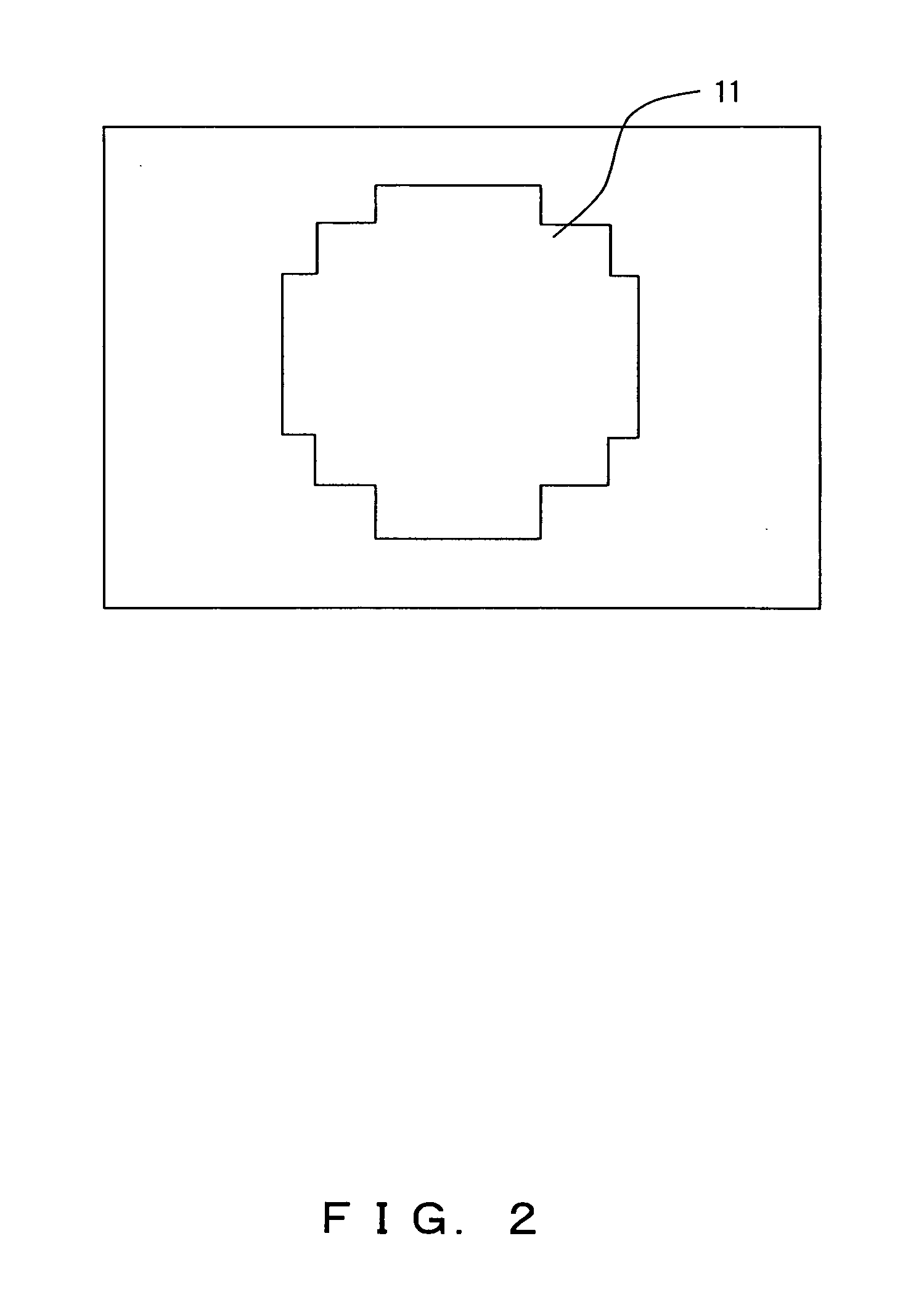
[0025] By approximating a boundary according to the pattern, the boundary can be more accurately expressed, compared with the conventional method of approximating a boundary along a surface constituting a cell. By predetermining the pattern, the number of calculation methods adopted to calculate both electric field intensity and magnetic field intensity can be suppressed or / and the calculation methods can be simplified. As a result, an electric / magnetic field analysis can be more accurately conducted while suppressing a calculation cost, without reducing a cell size. High generality can also be maintained.

Problems solved by technology

However, in the step approximation method, in reality, there is often a great difference between an expressed shape and an actual shape depending on its cell size.
The great difference in the shape of a boundary degrades analysis accuracy.
As the number increases, calculation cost, that is, necessary computer sources and calculation time increase.
However, the method requires modeling according to the shape of the analysis target object, which lacks generality.

Method used


Image

  • Electric/magnetic field analysis method using finite difference time domain, material descriptive method in electric/magnetic analysis, electric/magnetic analysis device, analysis data generation device and storage medium
  • Electric/magnetic field analysis method using finite difference time domain, material descriptive method in electric/magnetic analysis, electric/magnetic analysis device, analysis data generation device and storage medium
  • Electric/magnetic field analysis method using finite difference time domain, material descriptive method in electric/magnetic analysis, electric/magnetic analysis device, analysis data generation device and storage medium

Examples


Embodiment Construction

[0056] The preferred embodiments of the present invention are described in detail below with reference to the drawings.

[0057]FIGS. 3A through C and FIGS. 4A through C show the approximation methods of a boundary between materials in this preferred embodiment. FIGS. 3A through C show the approximation method in units of surfaces of a boundary between materials in the present invention. FIGS. 4A through C show the approximation method in units of cells of a boundary between materials in the present invention. Firstly, each approximation method, that is, the expression method of a material is described in detail with reference to FIGS. 3A-C and FIGS. 4A-C.

[0058] The centerline expressed in FIGS. 3A-C goes through the center of a surface constituting a cell and is parallel to one of the coordinate axes. Since a line parallel to one of the two coordinate axes can be disposed on the surface by the disposition way of a cell, there exit two parallel centerlines with different coordinate a...


PUM


Abstract

Two centerlines each of which goes through the center of a surface and is parallel to one of the coordinate axes are considered for each surface constituting a cell. If one of the centerlines intersects a boundary, a line which goes through the intersection and is orthogonal to the centerline is approximated as a new boundary. If a boundary intersects with each of the two centerlines, an orthogonal line expressed by each of two lines which is obtained by crossing each of the two centerlines parallel to each different coordinate axis and a boundary is approximated as a new boundary. Thus, the new boundary is expressed by each part of these orthogonal lines toward the centerline from their intersection.

Description

BACKGROUND OF THE INVENTION [0001] 1. Field of the Invention [0002] The present invention relates to a technology for conducting an electric / magnetic field analysis using a finite difference time domain method for dividing an analysis space by a polyhedron cell and differentiating a spatial domain. [0003] 2. Description of the Related Art [0004] For one of methods for conducting an electric / magnetic field analysis on antennas, electronic equipment and the like, a finite difference time domain (FDTD) method is used. The FDTD method is a finite difference method proposed by K. S. Yee. Since the FDTD method has an advantage that the necessary amount of memory is proportional to the number of cells, over other methods, attention is paid to the FDTD method as a useful method in the electric / magnetic field analysis. [0005] In the FDTD method, a spatial domain is differentiated by dividing an analysis space by a polyhedron called a cell. For the polyhedron, usually a hexahedron, that is, a...

Claims


Application Information

Patent Timeline
Patent Type & Authority Applications(United States)
IPC IPC(8): G01R29/08G06F17/50
CPCG06F2217/16G06F17/5018G06F30/23G06F2111/10
Inventor YAMAGAJO, TAKASHINAMIKI, TAKEFUMI
Owner FUJITSU LTD
Learn More