Washer, damper thereof, and control method thereof

a technology of damper and washer, which is applied in the direction of shock absorbers, braking systems, transportation and packaging, etc., can solve the problems of increasing the noise of the washer in the dewatering cycle, and increasing the noise of the dewatering cycle overall, so as to reduce the noise of the washer

Inactive Publication Date: 2005-09-01
LG ELECTRONICS INC
View PDF7 Cites 62 Cited by
  • Summary
  • Abstract
  • Description
  • Claims
  • Application Information

AI Technical Summary

Benefits of technology

[0016] An object of the present invention is to provide a washer, damper thereof, and control method thereof, by which washer noise

Problems solved by technology

However, the related art washer has the following problems.
First of all, the damper, which provides the same damping force in the excessive or normal vibration state, amplifies the vibration of the drum and the like in the normal vibration state, thereby increasing the noise in performing the dewatering cycle of the washer.
Secondly, the normal vibration state is mostly mai

Method used


Image

  • Washer, damper thereof, and control method thereof
  • Washer, damper thereof, and control method thereof
  • Washer, damper thereof, and control method thereof

Examples


first embodiment

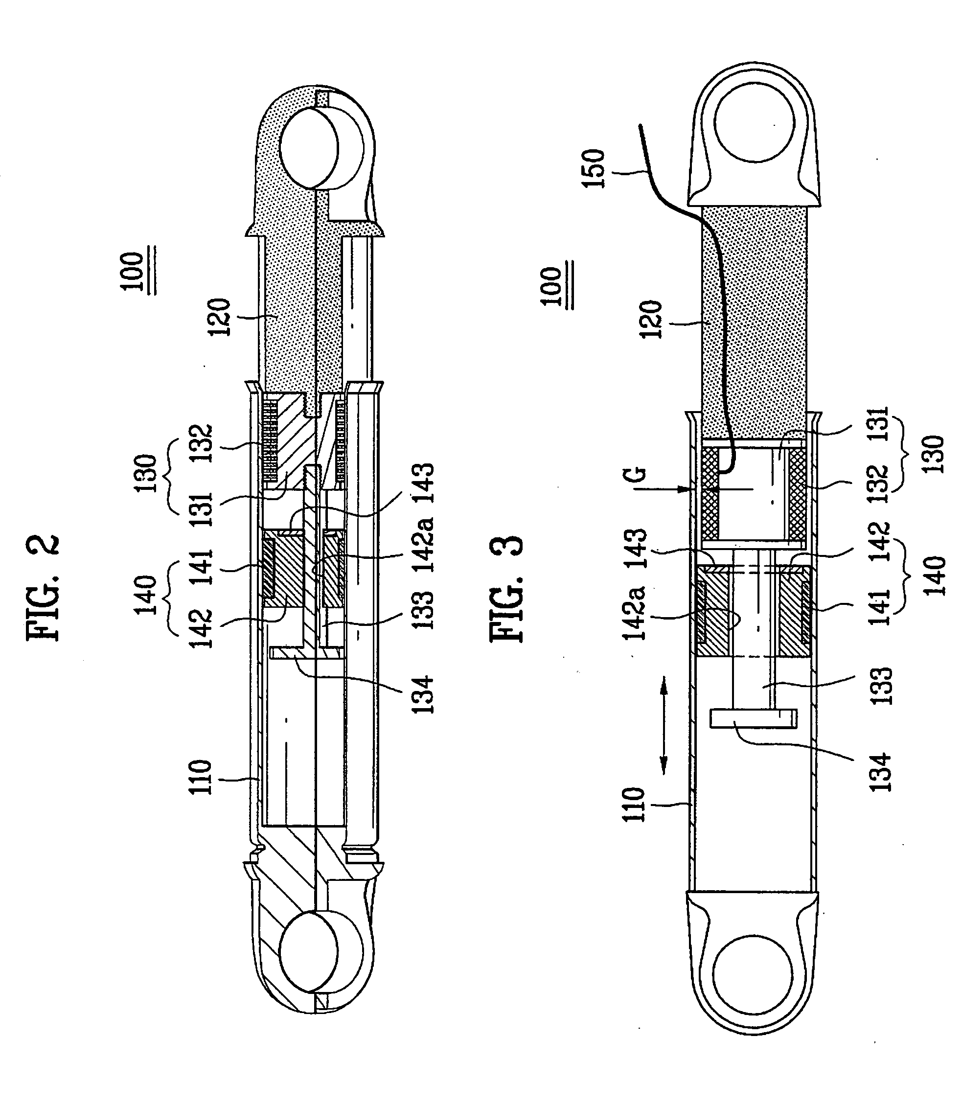
[0045] A damper according to the present invention is explained with reference to FIG. 2 and FIG. 3 as follows.

[0046] Referring to FIG. 2 and FIG. 3, a damper according to a first embodiment of the present invention includes a cylinder 110, a piston 120 coupled with the cylinder 110 to enable reciprocation motion and to generate a magnetic force by power impression, and a vibration-absorbing part 140 provided within the cylinder 110 to generate a frictional force by coming into contact with an inside surface of the cylinder 110 wherein the vibration-absorbing part 140 becomes attached to the piston 120 by the magnetic force to absorb vibration transferred to the cylinder 110 or the piston 120.

[0047] Preferably, the cylinder 110 has a cylindrical shape and the piston 120 has a rod shape. This is to prevent the damper 100 from being damaged because the piston 120 is rotated at a prescribed angle in a circumferential direction by vibration transferred from a vibrating body (e.g., wash...

second embodiment

[0077] An operation of the above-configured damper according to the present invention is explained as follows.

[0078] In the early stage of a dewatering cycle, if the control unit decides that the vibration of the tub is in the excessive vibration state, power is supplied to the magnetic force generating part 230 to generate the magnetic (attractive) force attributed to the reciprocal action between the bobbin 232 and the core 231. The magnetic force applies the attractive force to the steel member 245 fixed to the movable member 242 to attach the magnetic force generating part 230 and the vibration-absorbing part 240 together, which is shown in FIG. 7. In doing so, the guide 243 is most deeply inserted in the hollow portion 221. And, the sliding hole 231a of the magnetic force generating part 230 is operative in supporting the guide 243.

[0079] Once the magnetic force generating part 230 and the vibration-absorbing part 240 are attached together, the vibration transferred to the cyl...

third embodiment

[0083]FIG. 8 is a cross-sectional diagram of a damper according to the present invention, and FIG. 9 is a cross-sectional diagram of a damper for explaining an action of the damper in case that a magnetic force is generated from a magnetic force generator in FIG. 8.

[0084] Referring to FIG. 9, a magnetic force generating part 330 is inserted in a vibration-absorbing part 340 enable its reciprocating motion.

[0085] A guide 333 extends from a core 331 of the magnetic force generating part 330 in a length direction of a cylinder 310. The guide 333 is pressed to be inserted in the core 331. Alternatively, the guide 333 is screw-coupled with or built in one body of the core 331.

[0086] A bobbin 332 is provided to enclose the core 331. Preferably, the bobbin 332, as shown in FIG. 8, is provided not to be exposed to the cylinder. Of course, the bobbin 332 can be provided to be exposed to the cylinder 310. And, an outer circumference of the magnetic force generating part 330 is preferably pr...


PUM


Abstract

The present invention provides a washer, damper thereof, and control method thereof, by which noise is reduced by adjusting a damping force of the damper in a manner of turning on/off power of the damper according to an oscillation frequency of a vibrating body such as a washer. The control method reduces noise by supplying power to a damper in an excessive vibration state of a vibrating body such as a washer or by cutting off the power supplied to the damper in a normal vibration state of the vibrating body.

Description

[0001] This application claims the benefit of the Korean Application No. P2004-11826 filed on Feb. 23, 2004, which is hereby incorporated by reference. BACKGROUND OF THE INVENTION [0002] 1. Field of the Invention [0003] The present invention relates to a washer, damper thereof, and control method thereof. [0004] 2. Discussion of the Related Art [0005] Generally, a washer is an apparatus for washing the laundry using a water current and chemical reaction of a detergent and the like. The washer performs washing, heated washing, rinsing, and dewatering cycles selectively or collectively according to a user's selection. [0006] Washers are mainly categorized into a top-loading type washer and a front-loading type washer according to a laundry-loading system. A tub-rotating type washer and a pulsator type washer belong to the top-loading type washers. And, a drum type washer corresponds to the front-loading type washer. [0007] A tub is provided within a cabinet of the washer to store wate...

Claims


Application Information

Patent Timeline
IPC IPC(8): D06F29/00D06F33/00D06F37/22D06F37/20F16F7/09F16F9/12F16F15/03
CPCF16F7/09D06F37/20D06F37/22F16F15/03D06F39/125D06F33/48Y02B40/00
Inventor PARK, GWAN RYONGJEON, SI MOONPARK, SEUONG CHULKIMJUN, CHA SEUNGOH, SOO YOUNG
Owner LG ELECTRONICS INC
Why Eureka
Try Eureka