Inserts and method and apparatus for embedding inserts in cast members

Inactive Publication Date: 2005-09-01
POLY TEC PROD
View PDF29 Cites 2 Cited by
  • Summary
  • Abstract
  • Description
  • Claims
  • Application Information

AI Technical Summary

Benefits of technology

[0031] Still another object of the present invention is to provide a novel insert for use in a casting method and which is designed to prevent seepage of the cast material into the mechanism of the mold assembly.
[0033] Still another object of the present invention is to provide a novel insert for step members produced in either a wetcast or drycast method and having an internal serrated design which provides increased frictional holding forces acting against forces which may be applied in a direction to pull the step out of the insert.
[0035] It is still another object of the present invention to provide a novel two-piece insert for cast members produced during a casting method and which is adapted to seal the opening in the core mold member during casting of a mold member.

Problems solved by technology

The casting material entering into the openings in the region between the pins and the opening in the core member through which the pins extend, often renders the pins inoperative and possibly even causing damage to the mechanism.

Method used


Image

  • Inserts and method and apparatus for embedding inserts in cast members
  • Inserts and method and apparatus for embedding inserts in cast members
  • Inserts and method and apparatus for embedding inserts in cast members

Examples


embodiment 70

[0076] The two-piece insert assembly embodiment 70, shown in exploded fashion in FIG. 5, is comprised of first and second hollow, cylindrical-shaped, molded, plastic members 72 and 74. Member 72 has open ends 72a and 72b. A flange 72c provided intermediate ends 72a and 72b lies in a plane which is diagonally aligned relative to the central axis CL. Two (2) slots 72d are arranged at 180 degree intervals about the end 72b of member 72 and extend inwardly from end 72b toward flange 72c. Another set of two (2) slots 72e are arranged at 90 degree intervals about the end 72a of member 72 and extend inwardly from end 72a toward flange 72c. However, the inward end of slots 72e terminate a spaced distance from flange 72c. If desired, the number of slots 72d, 72e may be three or even four or more slots arranged a equi-spaced intervals about the circumference of member 72.

[0077] The major portion of member 72 extending between and 72a and flange 72c has a plurality of individual annular projec...

embodiment 60

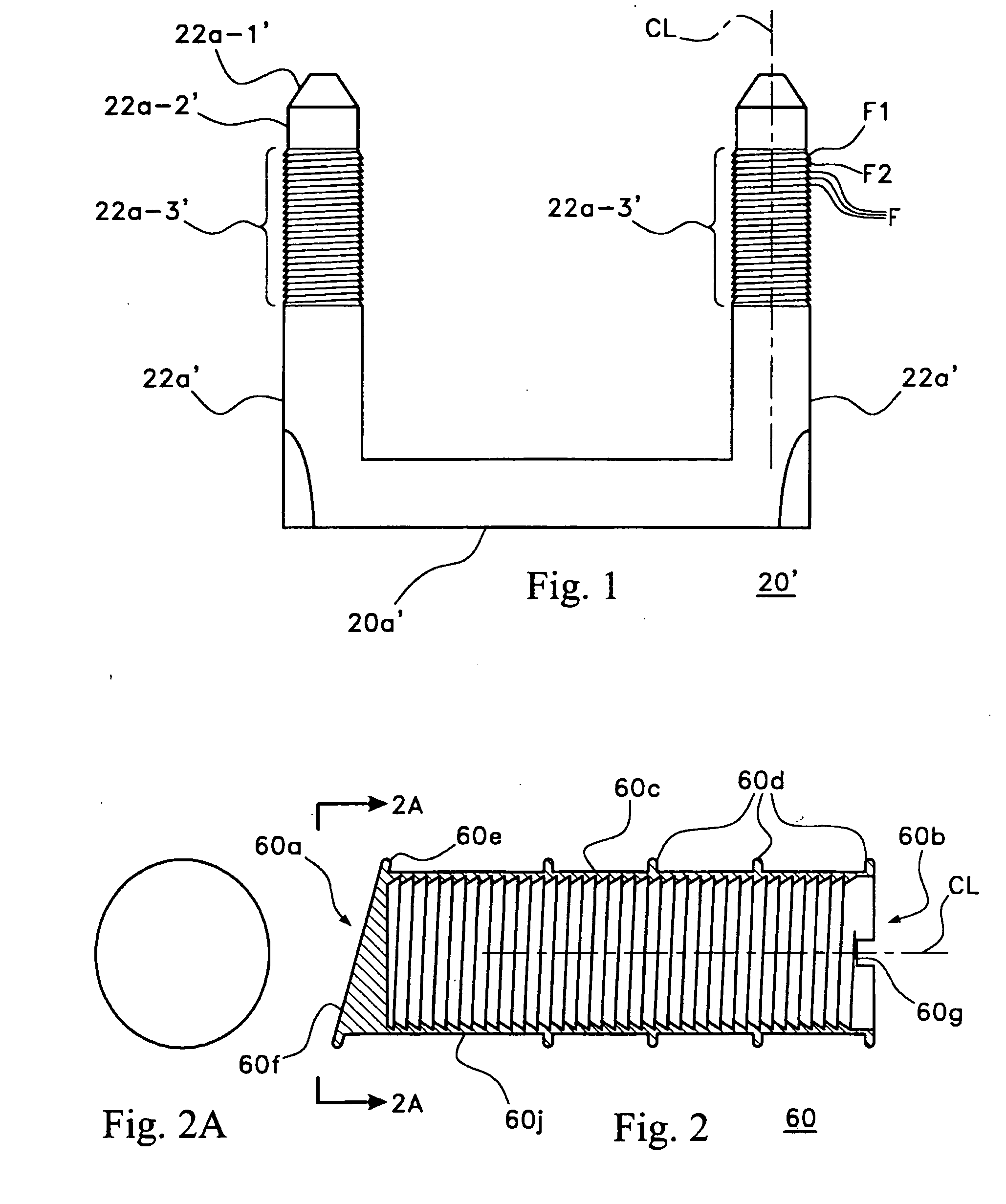
[0078] Insert member 74 has a closed end 74a and an open end 74b. End 74a has a planar surface which is diagonally aligned relative to center line CL and terminates in an integral annular flange, similar to the embodiment 60 shown in FIG. 2. The exterior of member 74 is further provided with a plurality of integral annular flanges 74c and 74c′, all of which are substantially planar and lie in planes forming right-angles with the center line CL.

[0079] The interior periphery of member 74 is provided with a plurality of closely spaced, inwardly directed, annular projections F″, having an inclined surface F1″ which is inclined at an angle to the longitudinal center-line CL and a surface F2″ which is substantially perpendicular to the center-line CL and which is on the side of the projection remote from the end 74b. This design is such as to make it easier for insertion of the end 72a into insert member 74, whereas any effort or attempt to pull the insert member 74 out of insert member 7...


PUM

PropertyMeasurementUnit
Thicknessaaaaaaaaaa
Forceaaaaaaaaaa
Flexibilityaaaaaaaaaa

Abstract

Method and apparatus for forming cast members having curved or flat walls. Steps are provided in the cast member by placing hollow plastic step inserts into holders provided along the inner core of a mold assembly or mounting inserts on reciprocating pins or mounting inserts to a marginal portion of the inner core. The cast material is then poured into the mold. The cast member, when set, is withdrawn from the mold assembly. In one embodiment, a holder portion of the step insert is broken away, leaving the step inserts embedded in the cast member to receive legs of manhole steps. The inserts are provided with flanges, preventing leakage of the cast material into the mold assembly. Similar seals are provided by other types of cylindrical-shaped inserts for use in wetcast and drycast fabrication methods. Mounting assemblies are also provided for holding inserts for embedment in planar walls.

Description

CROSS REFERENCE TO RELATED APPLICATION(S) [0001] This application is a continuation-in-part of U.S. patent application Ser. No. 09 / 395,106, filed Sep. 14, 1999, which is incorporated by reference as if fully set forth and which claims priority from provisional application Ser. No. 60 / 100,234, filed Sep. 14, 1998 and which provisional application is also incorporated by reference as if fully set forth.FIELD OF THE INVENTION [0002] The present invention relates to method and apparatus for producing cast concrete members and the like and more particularly to a method and apparatus for producing cast members which are provided with step inserts to facilitate insertion and firm gripping of steps in cast members. One embodiment of step inserts is designed to prevent undesirable seepage of the cast material and thereby retain the cast material within the mold assembly. Novel one-piece or two-pieces insert assemblies are provided to retain the insert in proper position during casting. The t...

Claims


Application Information

Patent Timeline
IPC IPC(8): B28B21/56B28B23/00E04B1/41E04G15/06E04G21/18E06C9/04
CPCB28B21/56B28B21/566B28B23/0056E06C9/04E04G15/063E04G21/185E04B1/4121
Inventor WESTHOFF, JAMES A.KELLY, JAMES A.
Owner POLY TEC PROD
Why Eureka
Try Eureka