Non-catalytic combustor for reducing NOX emissions

a nox emission, non-catalytic technology, applied in the ignition of turbine/propulsion engine, combustion type, lighting and heating apparatus, etc., can solve the problems of difficult rapid, uniform mixing, unstable lean flames, etc., and achieve the effect of improving the design of the combustor

Inactive Publication Date: 2005-09-01
SIEMENS ENERGY INC
View PDF14 Cites 22 Cited by
  • Summary
  • Abstract
  • Description
  • Claims
  • Application Information

AI Technical Summary

Benefits of technology

[0013]FIG. 1 is a functional diagram of a gas tu

Problems solved by technology

However, the difficulty with lean, premixed combustion is that the lean flames may be unstable, and additional steps may be necessary to ensure that the flame remains stable.
However, it is difficult to achieve rapid, uniform mixing of the injected air with the partially combusted rich fuel air mixture to quickly drive the overall mixture to a lean state while avoiding high temperature quasi-diffu

Method used


Image

  • Non-catalytic combustor for reducing NOX emissions
  • Non-catalytic combustor for reducing NOX emissions
  • Non-catalytic combustor for reducing NOX emissions

Examples


Embodiment Construction

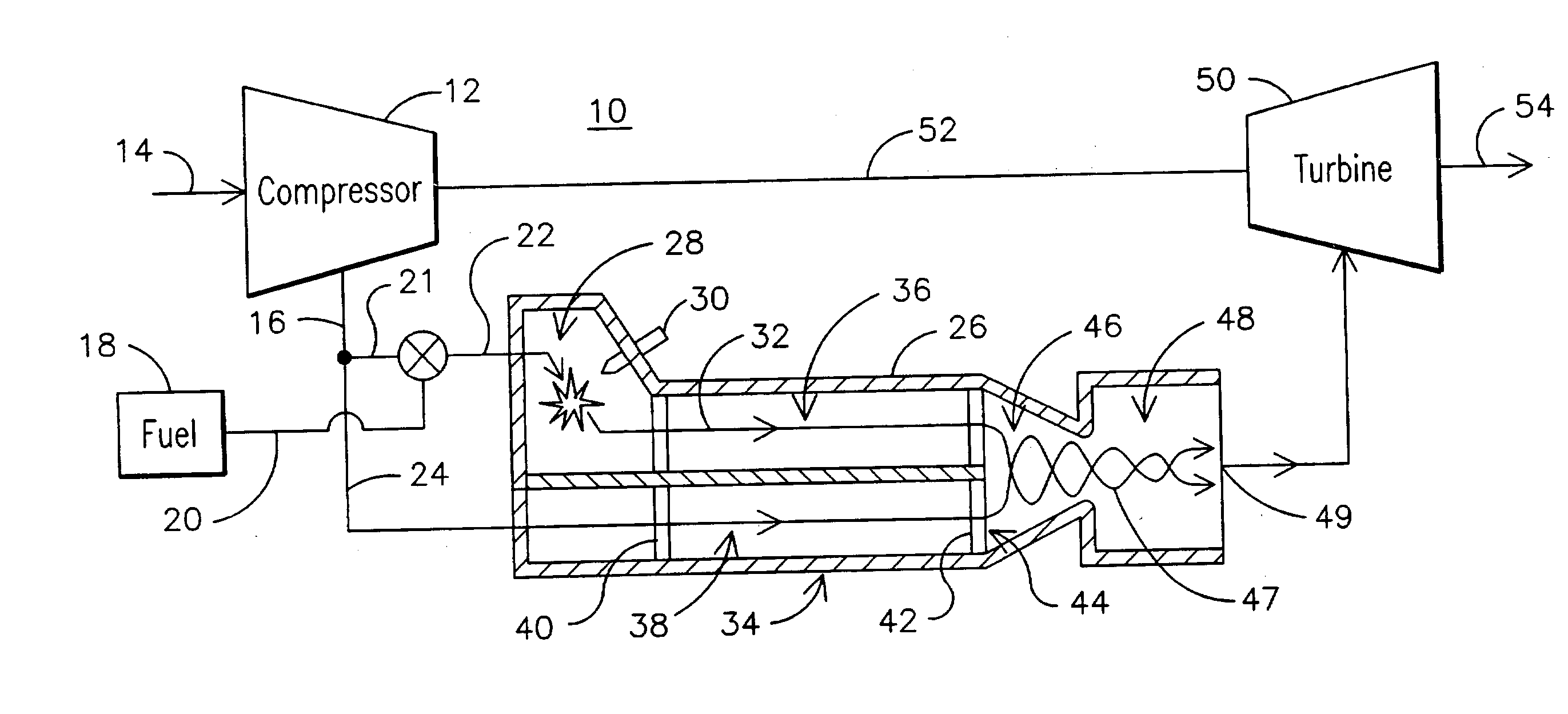
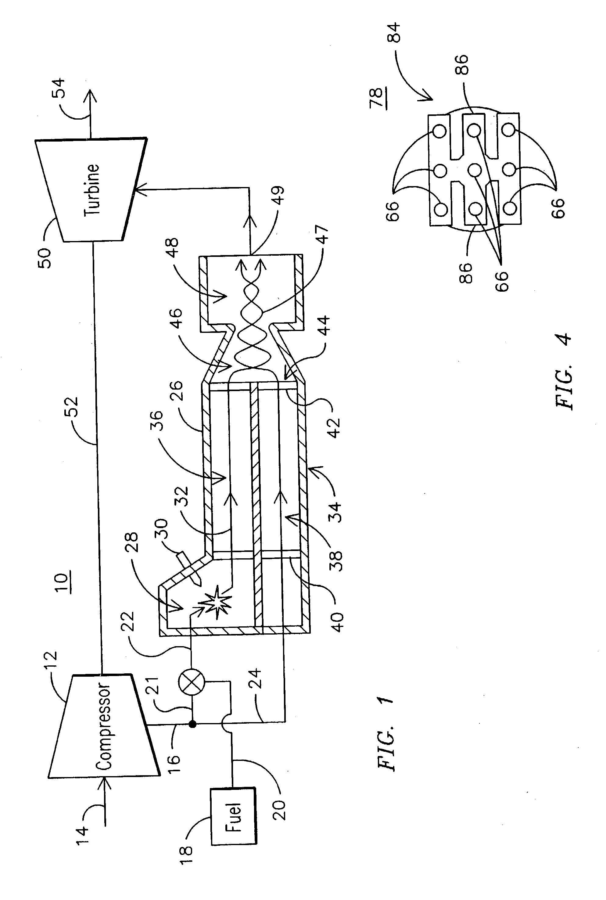
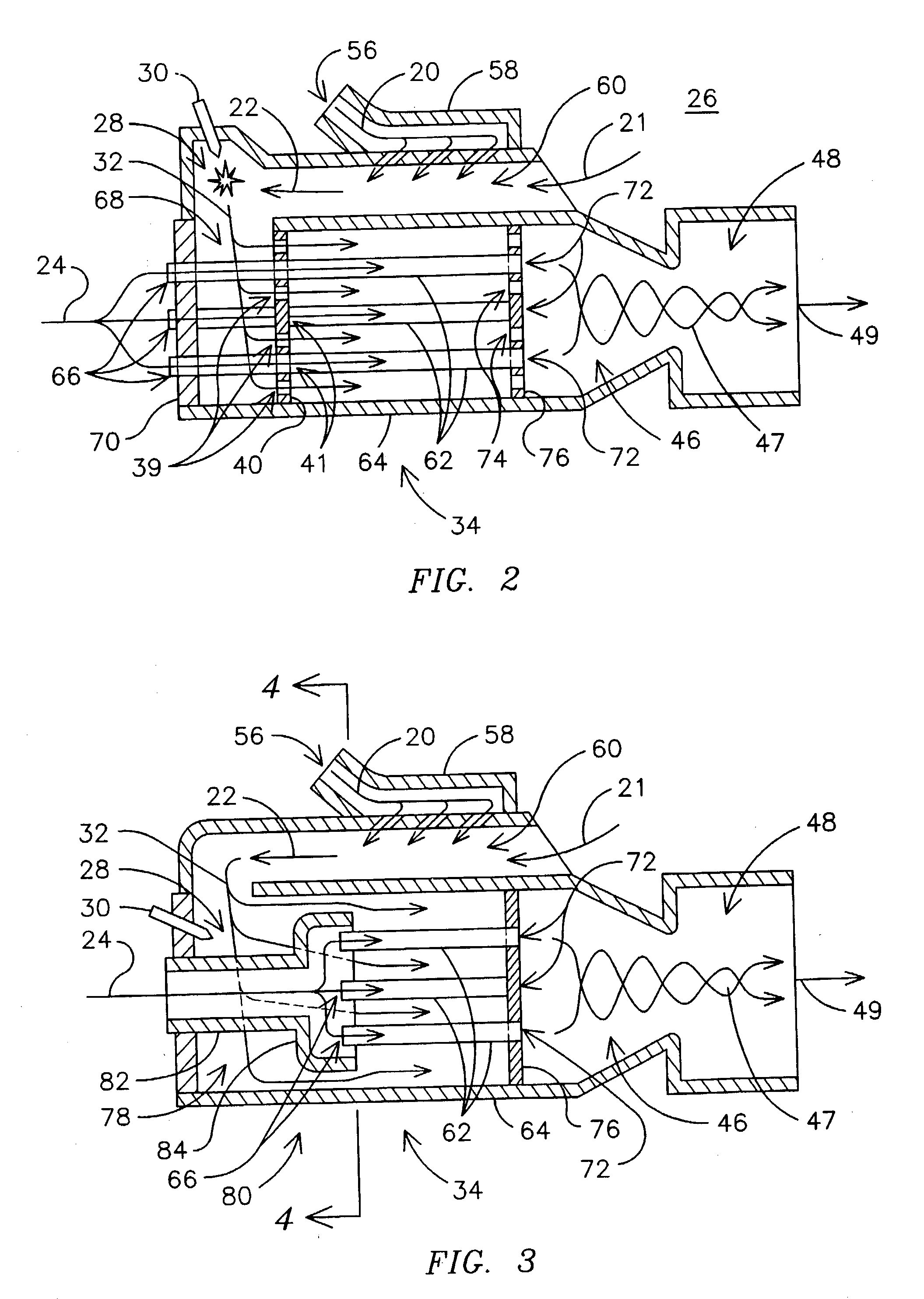
[0017]FIG. 1 illustrates a gas turbine engine 10 having a compressor 12 for receiving a flow of filtered ambient air 14 and for producing a flow of compressed air 16. The compressed air 16 is separated into a fuel mixing flow 21 and an oxidizer flow 24, respectively, for introduction into a combustor 26. The fuel mixing flow 21 is mixed with a flow of a combustible fuel 20, such as natural gas or fuel oil for example, provided by a fuel source 18, to create a fuel-rich fuel-oxidizer mixture flow 22 prior to introduction into a primary combustion chamber 28 of the combustor 26. In the primary combustion chamber 28, the fuel-oxidizer mixture flow 22 may be ignited by igniter 30 to form a partially oxidized mixture flow 32. From the primary combustion chamber 28, the partially oxidized mixture flow 32 is directed into a partially oxidized mixture flow channel 36 of a mixer element 34. The oxidizer flow 24 is directed into an oxidizer flow channel 38 of the mixer element 34 so that the ...


PUM

PropertyMeasurementUnit
Temperatureaaaaaaaaaa
Flame temperatureaaaaaaaaaa

Abstract

A gas turbine engine combustor (26) including a primary combustion chamber (28), a mixer element (34), a mixing chamber (46) and a secondary combustion chamber (48). The primary combustion chamber receives a fuel oxidizer mixture flow (22) and discharges a partially oxidized mixture flow (32). The mixer element includes a plurality of flow channels (36, 38) for separating the partially oxidized mixture from a flow of an oxidizer (24) and producing a plurality of partially oxidized mixture flows interspersed with a plurality of oxidizer fluid flows. The mixer element may include a plurality of tubes (62) retained by an upstream tubesheet (70) and a downstream tubesheet (76). The mixer element may function as a heat exchanger to heat the oxidizer fluid flow and to cool the partially oxidized mixture flow upstream of the post-mixing chamber.

Description

FIELD OF THE INVENTION [0001] This invention relates to combustors for gas turbines, and, in particular, to a non-catalytic combustor for reducing NOx emissions. BACKGROUND OF THE INVENTION [0002] Various combustor systems are well known in gas turbine applications to reduce the creation of pollutants in the combustion process. As known, gas turbines include a compressor for compressing air, a combustion stage for producing a hot gas by burning fuel in the presence of the compressed air produced by the compressor, and a turbine for expanding the hot gas to extract shaft power. The combustion process in many older gas turbine engines is dominated by diffusion flames burning at or near stoichiometric conditions with flame temperatures exceeding 3,000° F. Such combustion, however, typically produces a high level of oxides of nitrogen (NOx). Current emissions regulations have greatly reduced the allowable levels of NOx emissions. [0003] One method for reducing combustion temperatures is...

Claims


Application Information

Patent Timeline
IPC IPC(8): A23L1/30A61K38/56F23C6/04F23D14/66F23R3/28F23R3/34
CPCA23L1/3002A61K38/56F23C6/04F23R3/346F23D14/66F23R3/286F23C2900/06041A23L33/105Y02E20/34F23R3/28F23R3/34
Inventor BACHOVCHIN, DENNIS M.LIPPERT, THOMAS E.
Owner SIEMENS ENERGY INC
Why Eureka
Try Eureka