Shock absorbing lanyards

a technology of applied in safety belts, weaving, sport apparatus, etc., can solve the problems of manual relative length adjustment of webbings, and increased risk of falling and injury of workers and other personnel who have occupations which require them to be at elevated positions, etc., to improve shock absorption and lanyards, the effect of improving the shock absorption

Inactive Publication Date: 2005-09-01
YKK CORP OF AMERICA
View PDF16 Cites 68 Cited by
  • Summary
  • Abstract
  • Description
  • Claims
  • Application Information

AI Technical Summary

Benefits of technology

[0029] One advantage of the present invention is to provide improved lanyards, such as improved shock absorbing lanyards.
[0030] An advantage of the present invention is to automatically adjust the relative lengths of a high elongation member and a load bearing member of a shock absorbing lanyard.
[0031] Another advantage of the present invention is to form a shock absorbing lanyard by shrinking the length of a shock absorbing member relative to a load bearing web.
[0032] Another advantage of the present invention is to provide improved shock absorbing lanyards which have a shock absorbing member and a load bearing web woven together.
[0033] Yet another advantage of the present invention is to provide lanyards which can stop a person's fall while reducing the shock force to the person.
[0034] Further advantages of the present invention are to improve manufacturing of lanyards and reduce costs of lanyards.

Problems solved by technology

People who are at elevated positions above a floor or other relatively lower surface can be at risk of falling and injury.
For example, workers and other personnel who have occupations which require them to be at elevated positions, such as on scaffolding, can be at risk of falling and injury.
The relative length adjustment of the webbings is performed manually and is a significant disadvantage of existing lanyards.
Manufacture of the lanyards requires costly and tedious assembly processes, such as inserting the POY webbing through the tubular-shaped webbing.
The manufacturing process is complicated by proper control and manual setting of the critical relative lengths of the two webbings.

Method used


Image

  • Shock absorbing lanyards
  • Shock absorbing lanyards
  • Shock absorbing lanyards

Examples


Embodiment Construction

[0042] The present invention provides new lanyards. The present invention particularly provides new shock absorbing lanyards which can stop a person or object from falling and reduce shock to the person or object. One new shock absorbing lanyard according to the present invention has a shock absorbing member or web woven with a load bearing web. The present invention, however, can be practiced in many different embodiments.

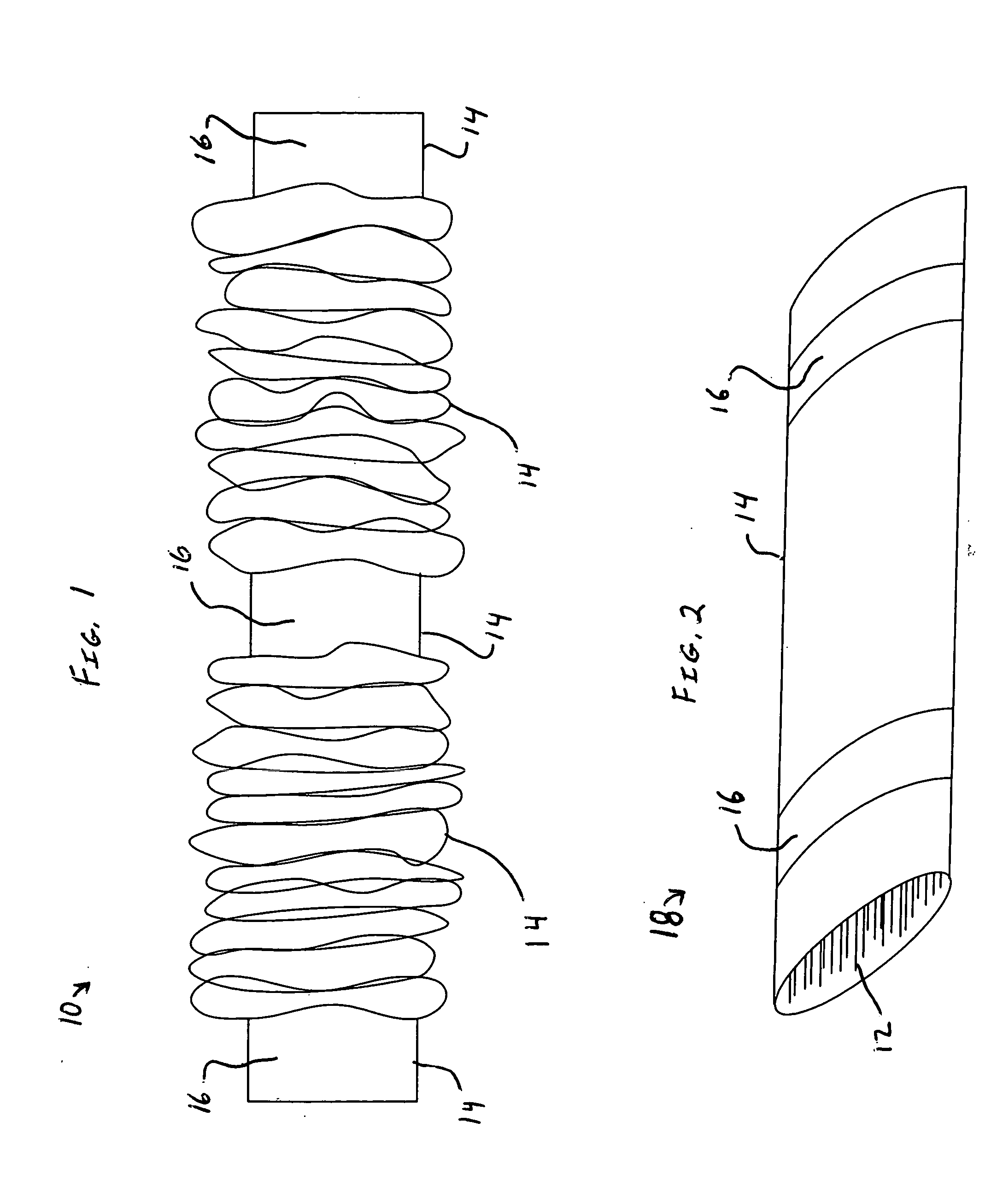
[0043] An example of the present invention is shown in FIG. 1 which shows a shock absorbing lanyard 10. The shock absorbing lanyard 10 is a woven webbing having high elongation yarns 12 (see FIG. 2) inside of a woven outer sheath or shell 14 of high strength yarn. The high elongation yarns 12 are highly extensible and significantly stretch when placed under a suitable tensile load. The high elongation yarns 12 can have any desired configuration, such as woven together or non-woven, for example. The high elongation yarns 12 are one example of shock absorbing membe...


PUM


Abstract

A shock absorbing lanyard is a one-piece webbing. The shock absorbing lanyard has a tubular-shaped high strength outer sheath and a high elongation member inside of the outer sheath. The outer sheath and the high elongation member are secured together at spaced apart connection locations and the high elongation member is generally not secured to the outer sheath between the connection locations. Heat treatment shrinks the length of the high elongation member. The outer sheath does not substantially shrink from the heat treatment relative to the high elongation member and gathers together in an accordion-like arrangement. A tensile load applied to the lanyard stretches the high elongation member and unfolds the gathered outer sheath. The high strength outer sheath supports the tensile load when completely unfolded while the high elongation member absorbs energy as it stretches or elongates.

Description

BACKGROUND OF THE INVENTION [0001] The present invention generally pertains to lanyards and shock absorbing lanyards. More specifically, the present invention pertains to shock absorbing lanyards having a shock absorbing member and a load bearing web. The relative lengths of the shock absorbing member and the load bearing web are automatically adjusted. Also, the shock absorbing member and the load bearing web may be woven together. The present invention further pertains to methods of making shock absorbing lanyards. The present invention provides improved lanyards which can elongate, absorb energy and support a load. [0002] People who are at elevated positions above a floor or other relatively lower surface can be at risk of falling and injury. For example, workers and other personnel who have occupations which require them to be at elevated positions, such as on scaffolding, can be at risk of falling and injury. Safety harnesses can be worn to stop a person's fall and prevent or r...

Claims


Application Information

Patent Timeline
Patent Type & Authority Applications(United States)
IPC IPC(8): A47L3/04A62B35/04D03D3/02D03D11/00D03D11/02
CPCA62B35/04D03D11/02D03D11/00D03D3/02
Inventor TANAKA, HAJIMERUSSELL, TIM
Owner YKK CORP OF AMERICA
Why Eureka
Try Eureka