

Controllable microscopic bubble nucleation in fluid polymer material production method and its apparatus
- Summary
- Abstract
- Description
- Claims
- Application Information
AI Technical Summary
Benefits of technology
Problems solved by technology
Method used
Image

Examples
first embodiment
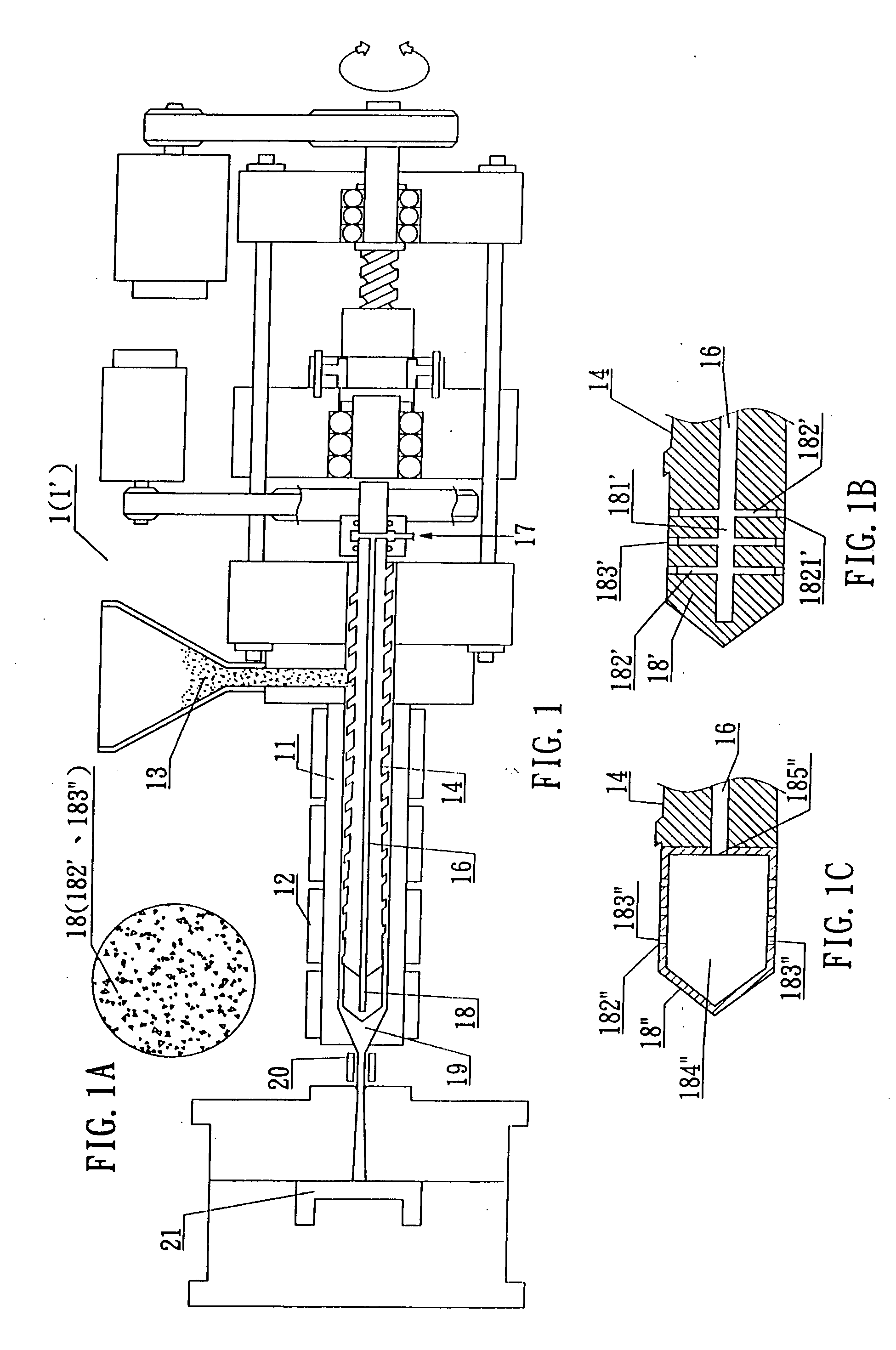
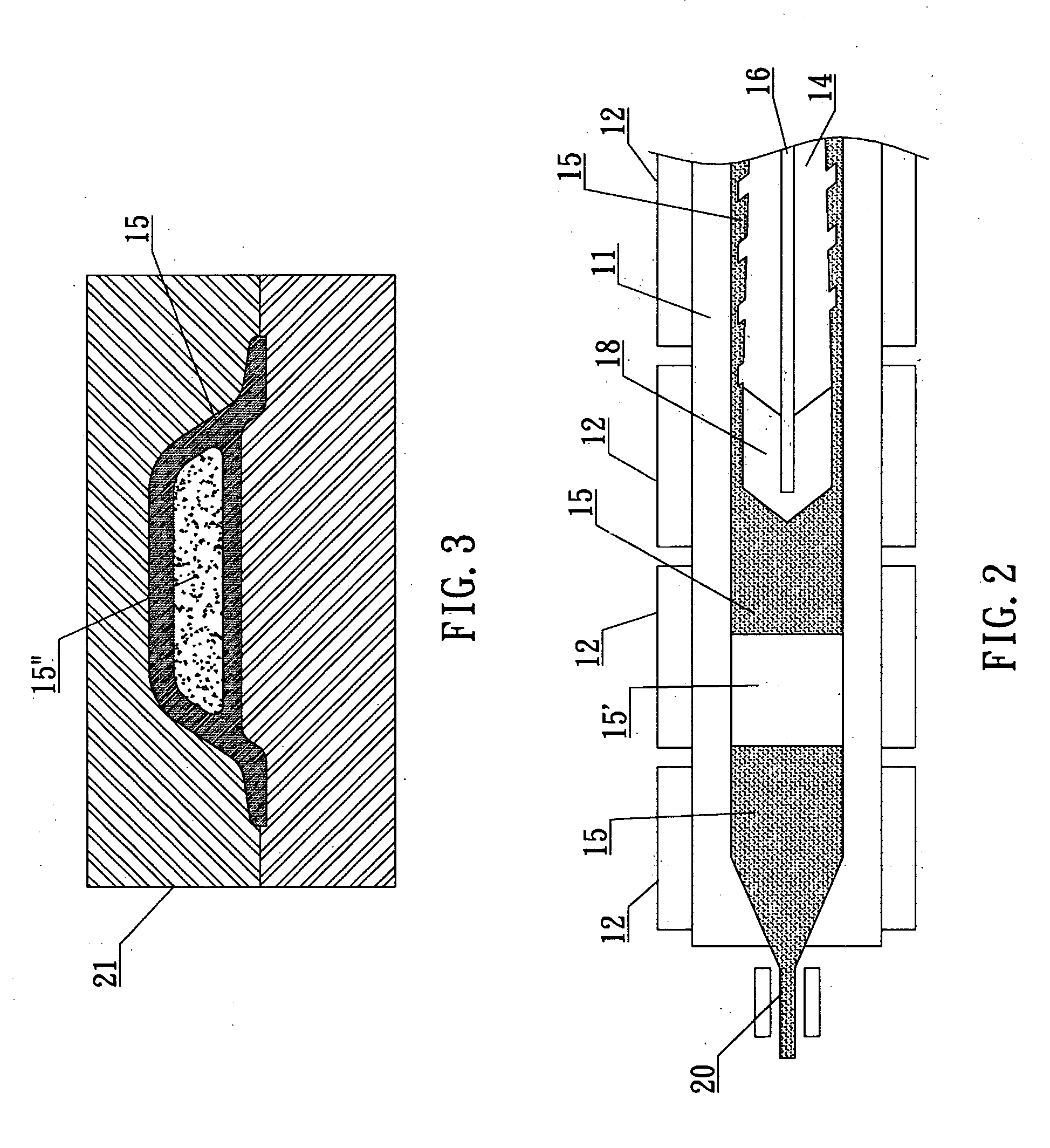
[0024] the invention herein, referring to FIG. 1 and FIG. 1-A, utilizes a materials pipe 11 inside an injector or an extractor 1 (1′) having a heater 12 outside to melt polymer material 13 which is transferred and blended along a conveyance screw shaft 14, the molten liquid polymer material 15 thereby pushed forward; the said foaming source utilized involves the gaseous precipitation of a foaming reaction in the polymer material; a gas pipe 16 is disposed in the conveyance screw shaft 14, an air intake opening 17 is situated at the rear extremity and connected to a pressurization pump or a high pressure gas storage tank and, furthermore, a microbubble generating component 18 (such as a microscopic perforation vented metal head or a microscopic perforation ceramic head, etc.) is installed at the front extremity of the conveyance screw shaft 14; the said microbubble generating component 18 (such as a microscopic perforation vented metal head or a microscopic perforation ceramic head, ...
fourth embodiment
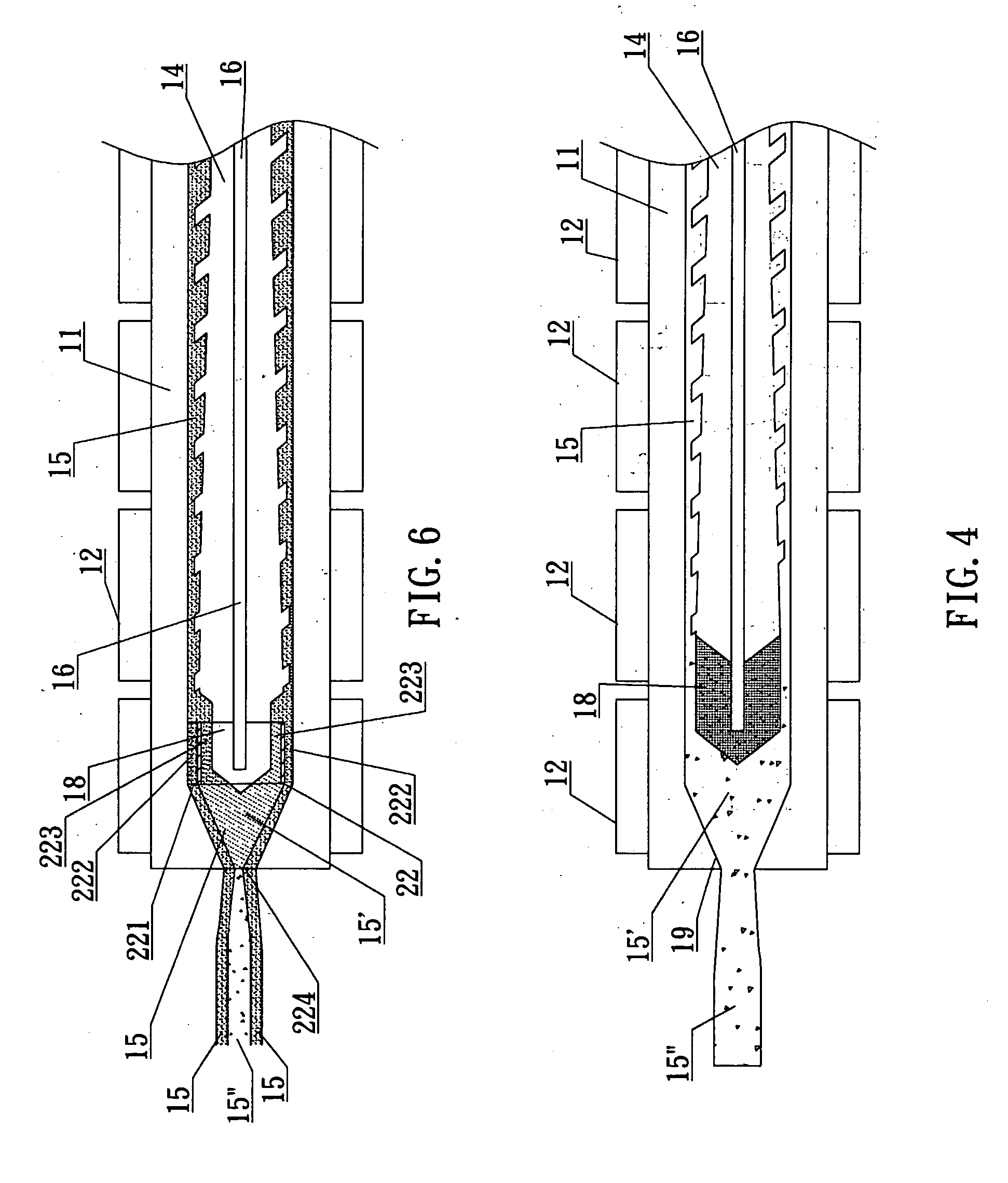
[0030] the invention herein, referring to FIG. 5-A, FIG. 5-B, and FIG. 5-C, consists of an apparatus in which when the extractor is utilized to draw out the polymer material, the non-nucleated is maintained at the outer portion of the said extracted polymer material so that the surface is glossy and the nucleated is generated at the inner portion; a flow diverter ring 22 is sleeved onto the front end of the microbubble generating component 18 and ribs 221 are formed lengthwise along the outer edges of the said flow diverter ring 22 such that the height between the outer edges of the flow diverter ring 22 and the materials pipe 11 defined by the lengthwise ribs 221 form a non-microbubble permeated polymer material channel 222, while that between the inner edge of the flow diverter ring 22 and the microbubble generating component 18 form a microbubble permeated polymer material channel 223; as a result, referring to FIG. 5-C and FIG. 6, the said liquid polymer material 15 is pushed fo...
PUM
| Property | Measurement | Unit |
|---|---|---|
| Length | aaaaa | aaaaa |
| Temperature | aaaaa | aaaaa |
| Pressure | aaaaa | aaaaa |
Abstract
Description
Claims
Application Information