
Liquid crystal display device and backlight module thereof and light assembly of backlight module

a technology of backlight module and display device, which is applied in the direction of optics, instruments, optical light guides, etc., can solve the problems of easy protrusion of illumination and light leakage, increase the difficulty of manufacture of optical sheets, and difficulty in attaching adhesive tapes, etc., and achieves the effect of convenient attachmen

Inactive Publication Date: 2005-09-01
HANNSTAR DISPLAY CORPORATION
View PDF8 Cites 5 Cited by
  • Summary
  • Abstract
  • Description
  • Claims
  • Application Information

AI Technical Summary

Benefits of technology

[0011] Accordingly, it is an object of the present invention to provide a lamp assembly which is applied to a backlight module of a liquid crystal display device and includes a lamp holder having a novel stopper for preventing a optical sheet from contacting a lamp, thereby solving the above-mentioned problems in the prior art.
[0016] Preferably, the lamp holder further includes at least one second stopper, e.g. two stoppers which are respectively disposed near the two ends of the lamp holder. The second stoppers are formed by cutting and bending the lower wall of the lamp holder. The optical sheet has at least one concave corresponding to the second stoppers for snapping to the second stoppers so as to mount the optical sheet. The contact between the second stoppers and the optical sheet can be plane, line or point so as to restrict the optical sheet to be removed forward or backward in the direction of the lamp. In other words, the freedom degree of the direction of the lamp is restricted, and therefore during ramming test the present invention can prevent the optical sheet separating from the housing so as to increase the durability of the backlight module.
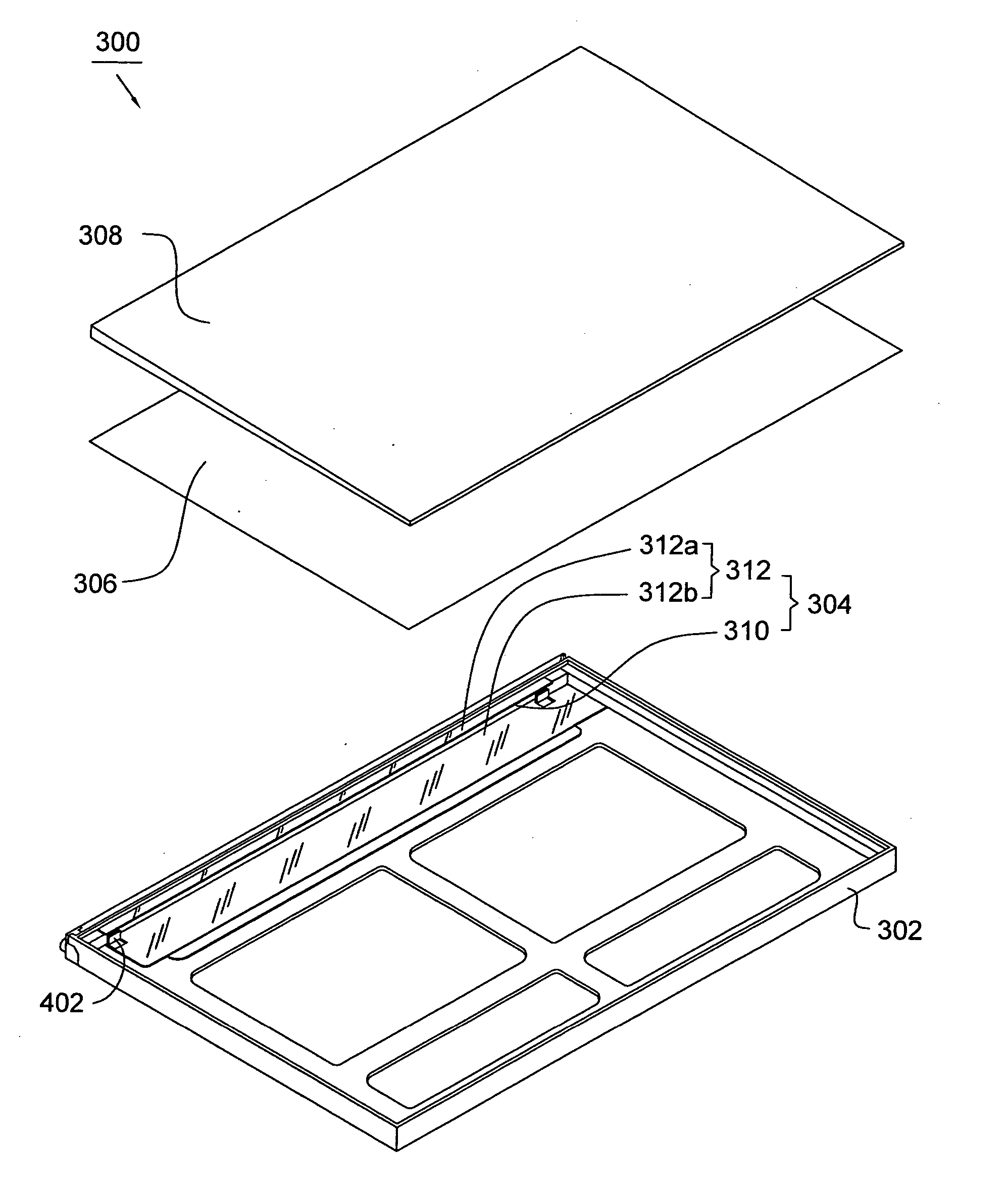
[0018] The lamp assembly of the present invention has a novel stopper. When the stopper is disposed on a backlight module, the stopper is disposed between the lamp and the optical sheet, thereby preventing the optical sheet from contacting the lamp. Thus, when the lamp assembly is applied to the backlight module, the optical sheet can be a structure without the protrusion, thereby solving the problem of the optical design of the protrusion of the optical sheet, making it easier to attach the adhesive tape to the side of the optical sheet, or fully omitting the adhesive tape.

Problems solved by technology

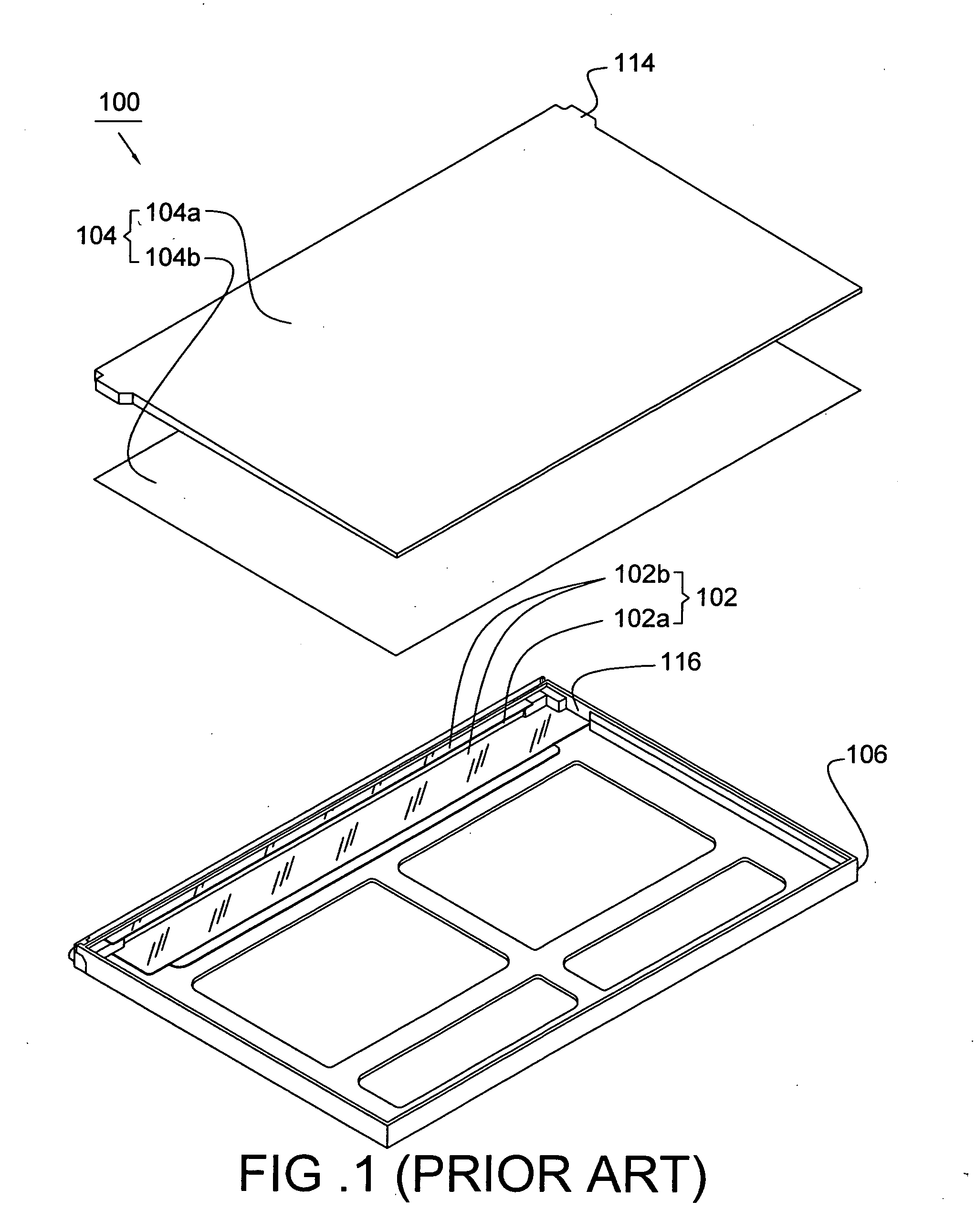
However, the geometric figure of the protrusions 114 is different from the geometric figure of other position of the light guide plate 104a, and therefore there are problems of uneven illumination and light leakage easily at the protrusions 114.
For above reasons, the protrusions of the optical sheet must be specially designed to improve the optical property, but it will increase the difficulty of manufacture of the optical sheet.
However, it is difficult to attach the adhesive tape because the protrusion 114 is provided.
Furthermore, the adhesive tape is not easily securely attached to the protrusion 114.
However, when the liquid crystal display device is large dimension, it will increase difficulty of manufacture of the frame because the frame is rectangular structure and must match with the fixing unit.
Furthermore, the fixing unit is an additional component and therefore the whole cost of the liquid crystal display device can be also increased.

Method used


Image

  • Liquid crystal display device and backlight module thereof and light assembly of backlight module
  • Liquid crystal display device and backlight module thereof and light assembly of backlight module
  • Liquid crystal display device and backlight module thereof and light assembly of backlight module

Examples


Embodiment Construction

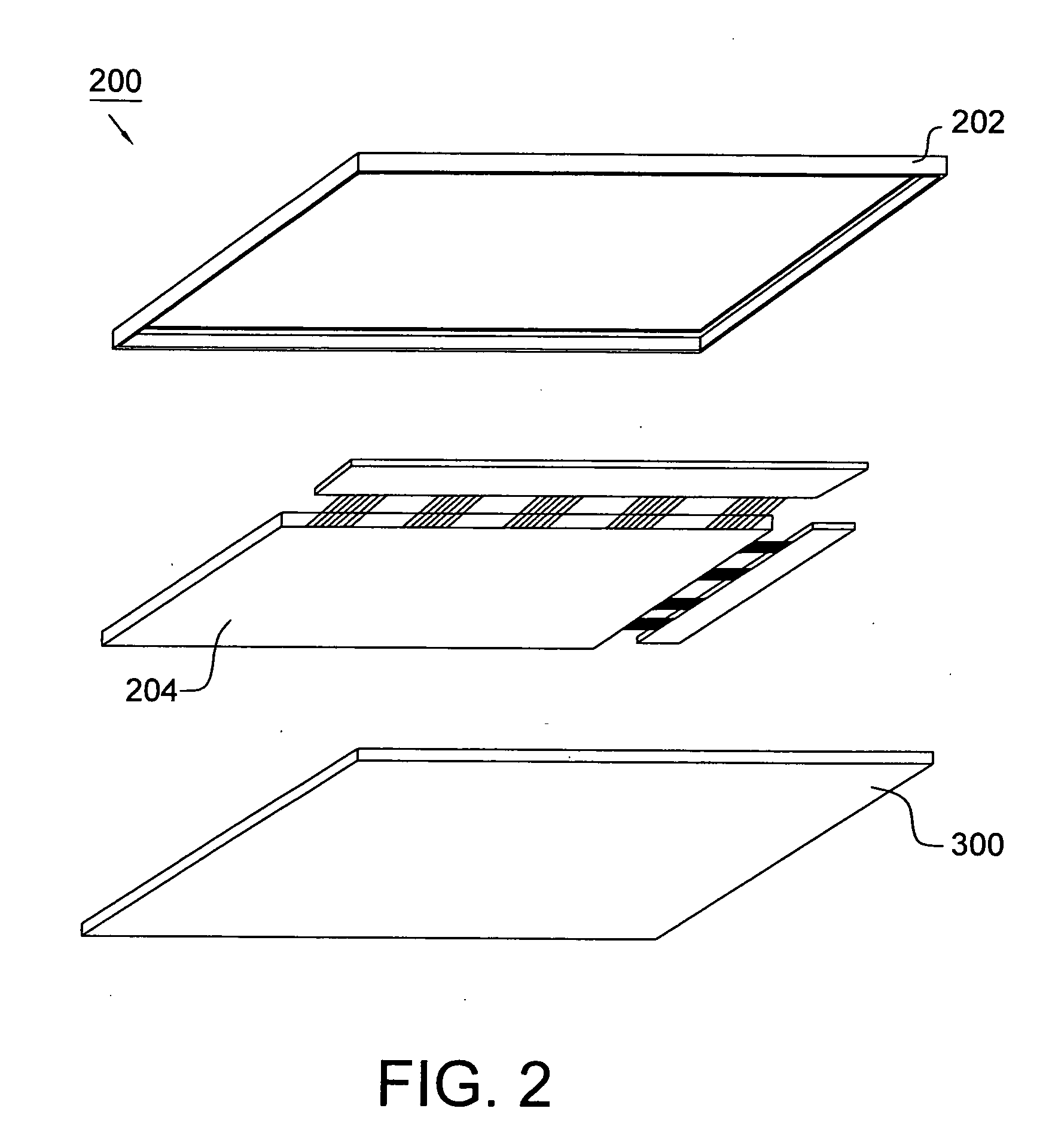
[0029] Referring to FIG. 2, it depicts a liquid crystal display device 200 according to an embodiment of the present invention. The liquid crystal display device 200 includes a frame 202, a liquid crystal panel 204 for displaying image and a backlight module 300 for providing the liquid crystal panel 204 with a light source.

[0030] As shown in FIG. 3, the backlight module 300 includes a housing 302, a lamp assembly 304, a reflective sheet 306 which is disposed in the housing 302, and a optical sheet 308 which is disposed on the reflective sheet 306, wherein the optical sheet 308 is a light guide plate in this embodiment. But in another embodiment, the optical sheet 308 is a diffuser plate or others just according to design. The light assembly 304 includes a lamp 310 being the light source and a lamp holder 312. The back light module 300 is utilized to distribute the light from a light source uniformly over the surface of the liquid crystal panel 204 (shown in FIG. 2).

[0031] The hou...


PUM


Abstract

A light assembly mainly includes a lamp and a lamp holder. The lamp has a pair of first ends and the lamp holder has a pair of second ends, wherein the second ends of the lamp holder are coupled with the first ends of the lamp. The lamp holder includes a pair of stoppers on the second ends of the lamp holder. The present invention further provides a backlight module using the light assembly therein, and a liquid crystal display device using the backlight module therein.

Description

[0001] This application claims the priority benefit of Taiwan Patent Application Serial No. 092134609, filed Dec. 18, 2003 and Taiwan Patent Application Serial No. 093107086, filed Mar. 17, 2004, the full disclosures of which are incorporated herein by reference. BACKGROUND OF THE INVENTION [0002] 1 Field of the Invention [0003] The present invention generally relates to a liquid crystal display device, and more particularly to a backlight module thereof. [0004] 2. Description of the Related Art [0005] Typically, the liquid crystal display device includes a liquid crystal panel (which has two substrates and a liquid crystal layer sealed therebetween) and an illuminative means, e.g. a backlight module mounted under the liquid crystal panel. The back light module is utilized to distribute the light from a light source uniformly over the surface of the liquid crystal panel. [0006] As shown in FIG. 1, the backlight module 100 includes a lamp assembly 102 and a series of stacked sheets 1...

Claims


Application Information

Patent Timeline
IPC IPC(8): F21V8/00G02F1/1333
CPCG02B6/009
Inventor WAN, CHIEN MINGLEE, ESZU FONGHUANG, SHENG HAOCHEN, CHEN-YUAN
Owner HANNSTAR DISPLAY CORPORATION
Learn More