Self calibrating media edge sensor

a sensor and edge technology, applied in the field of media sensors, can solve the problems of degrading the response characteristics of the sensor circuit, affecting and reducing the random error of the signal response, so as to reduce the effect of ambient ligh

Active Publication Date: 2005-09-01
ZEBRA TECH CORP
View PDF56 Cites 37 Cited by
  • Summary
  • Abstract
  • Description
  • Claims
  • Application Information

AI Technical Summary

Benefits of technology

[0102] As mentioned above, the embodiments may use a collimating light source such as a side emitting laser or VCSEL. As illustrated in FIG. 19, the light source and sensors for detecting the presence of a label may be located either outside or near an ope

Problems solved by technology

Noise generated in part by the presence of paper fibers or other non-uniformities in the web and or labels introduces a further random error to the detector by varying the point, relative to the actual edge location, at which a preset transition threshold signal level is detected.
Further, environmental fouling of the emitter, aperture and or detector will degrade sensor circuit response characteristi

Method used


Image

  • Self calibrating media edge sensor
  • Self calibrating media edge sensor
  • Self calibrating media edge sensor

Examples


first embodiment

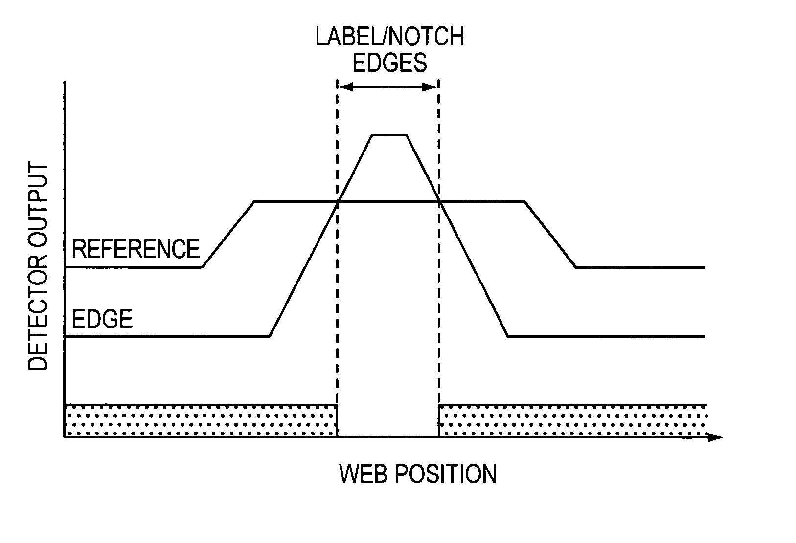
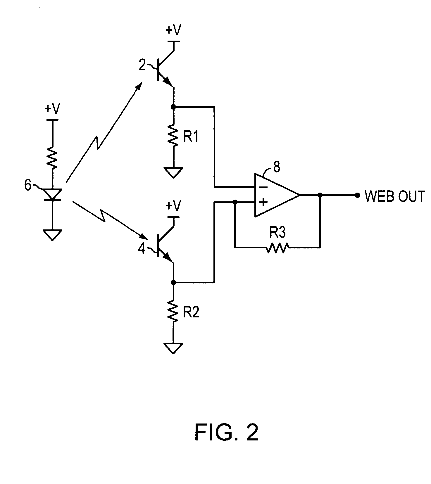
[0041] the invention uses an energy emitter that illuminates, through the media, a reference sensor 2 and an edge sensor 4. A simplified electrical schematic of the sensor circuit is shown in FIG. 2. The reference sensor 2 and the edge sensor 4 sense the first emitter 6 output passing through the web between each label. The output of each sensor is input to a comparator 8 that switches state when the edge signal level exceeds the reference signal level. To ensure that the steady state “high” reference signal level is below the edge signal “high” level, a bias may be introduced via modifications to the aperture dimensions and or adjusting components. In one embodiment, as illustrated in FIG. 2, the bias may be introduced by adjusting a pair of pull-down resistor values so that R1 is larger than R2. More generally, however, the bias can be introduced in a variety of ways including deliberate sensor mismatching, differences in corresponding parts (e.g., pull-down resistor values, etc.)...

second embodiment

[0045] the invention is selectable between dual modes. In a first mode, the circuit operates as described above, monitoring web transmissivity changes resulting from spaces between labels. In a second mode, the circuit monitors web reflectivity changes resulting from passage of black mark(s) 20 placed on the back side of the web. As shown in FIG. 8A, to add the second mode, a second emitter 18 is located proximate the edge sensor 2 and the reference sensor 4 to illuminate the sensor side of the web 13. If closed loop feedback is used for the first emitter 6 supply current level as described herein above, the second emitter 18 may be similarly configured.

third embodiment

[0046] the invention includes a “reflective-only” version. As shown in FIG. 8B, this embodiment does not require the presence of the emitter 6. Thus, rather than being selectable between dual modes, the circuit need only be configured to monitor web reflectivity changes resulting from the passage of black mark(s) 20 placed on the back side of the web. To do so, the emitter 18, as shown in FIG. 8B, is located proximate the edge sensor 2 and the reference sensor 4 to illuminate the sensor side of the web 13. As with the other embodiments, closed loop feedback can be used for the emitter 18 supply current level as described herein above.

[0047] With the circuit in black mark detecting mode, the first emitter 6 is disabled and the second emitter 18 is energized. As shown by the signal level progression in FIG. 9, the circuit operates with an inverted steady state as both the reference sensor 2 and the edge sensor 4 receive the second emitter 18 output reflection from the web, causing ele...


PUM


Abstract

Various edge detection arrangements are disclosed, including an edge detection method and arrangement that utilizes outputs of commonly illuminated reference and edge sensors as the inputs for a comparator. The reference sensor is configured to have a wide field of view and the edge sensor is configured to have a narrow, high gain, field of view. Therefore, the reference sensor has a broad signal response to an edge passage and the edge sensor a steep and narrow signal response. When the two signals are biased to cross each other, the comparator output changes state, indicating passage of an edge. Because the reference sensor provides a base signal level directly related to the real time illumination level that the edge sensor also receives, the reference sensor provides a switch point along the transition ramp of the edge sensor that integrates a majority of the random error sources.

Description

CROSS REFERENCE TO RELATED APPLICATIONS [0001] This application claims priority from U.S. provisional application Ser. No. 60 / 481,974 filed Jan. 30, 2004, which is titled “Self Calibrating Media Edge Sensor,” and which is hereby incorporated by reference.BACKGROUND OF INVENTION [0002] 1. Field of the Invention [0003] The present invention relates to media sensors. More specifically, the present invention provides methods and arrangements for media edge sensors useful, for example, in a label printer. [0004] 2. Description of Related Art [0005] Edge detection is used for identifying the passage of leading and or trailing edges of media as a means for counting and or accurate spatial registration of operations to be performed upon desired areas of the media. For example, label printers pass an array of labels releasably adhered to a support web past a printhead. An emitter and a detector pair are positioned on either side of the support web to detect changes in the web transmissivity ...

Claims


Application Information

Patent Timeline
IPC IPC(8): B65C9/18B65C9/42B65H37/00G01N21/84
CPCB65C9/42
Inventor EHRHARDT, ROBERT A. JR.SCHWAN, MARTIN ANDREAS KARLSMOLENSKI, LAWRENCE EDWARDMASTINICK, PHILIP ALANSEVERANCE, PHIL ROSS
Owner ZEBRA TECH CORP
Why Eureka
Try Eureka