Transmitter device for controlling data transmission

a technology of transmitter device and data transmission, which is applied in the field of improving transmission efficiency, can solve the problems of degrading transmission efficiency, congestion, and increasing propagation delay between a transmitter device and a receiver device, so as to avoid excessive transmission of data blocks, and reduce the frequency of retransmission

Inactive Publication Date: 2005-09-01
NTT DOCOMO INC
View PDF4 Cites 27 Cited by
  • Summary
  • Abstract
  • Description
  • Claims
  • Application Information

AI Technical Summary

Benefits of technology

[0017] According to the present invention, a time value corresponding to propagation delay in a communication link is determined in advance to be set as a retransmission timeout value during a time period existing between first-time transmission of a data block and immediately before second-time transmission of the data block, to thereby reduce occurrences of retransmission initiated when a data segment that is regarded as lost, in actuality, is not lost. Further, according to the present invention, in a transmitter device or in a computer by which the program is executed, a retransmission timeout value is set to a value corresponding to at least one of an upper limit for a transfer time of data and that for a number of times of transmission of the same data, to thereby reduce instances of retransmission resulting from a data segment that has not been lost being regarded as lost.
[0018] Further, according to the present invention, in a transmitter device or in a computer by which the program is executed, a retransmission timeout value for a data block increases every time the data block is transmitted during a given time period after a second-time transmission of the data block, it is possible to avoid excessive transmission of data blocks into an already congested communication network, to thereby avoid any further increase in congestion in a communication network and to increase transmission efficiency.

Problems solved by technology

Since data transmission in a wireless link is more likely to experience data propagation delay as compared to that in a wired link, such retransmission in a wireless link is likely to cause more propagation delay between a transmitter device and a receiver device which transmit and receive segments over a wireless link which is a part of a communication path.
However, since a retransmission timeout value is fixed to a certain value if the techniques described in JP 2003-102057 and JP 2003-224619 are applied, congestion is likely to further deteriorate in a communication network between a transmitter device and a receiver device.
Nevertheless, use of an initial value of a retransmission timeout value which is a relatively large value and an exponential increase of a retransmission timeout value thereafter results in rough-spacing retransmission timeout at the beginning of retransmission control, which in turn degrades transmission efficiency.

Method used


Image

  • Transmitter device for controlling data transmission
  • Transmitter device for controlling data transmission
  • Transmitter device for controlling data transmission

Examples


Embodiment Construction

[0033] Description will be given of an embodiment of the present invention with reference to the attached drawings.

Configuration

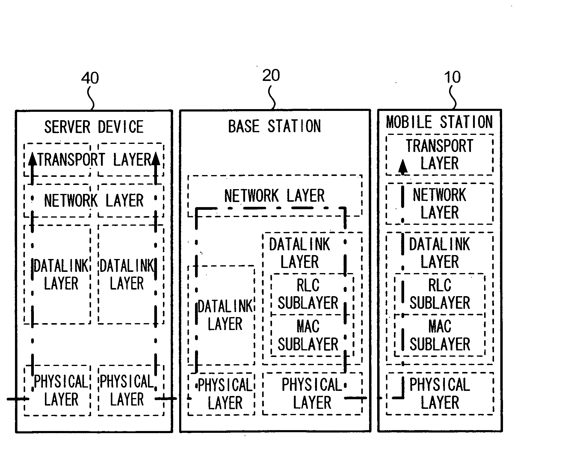
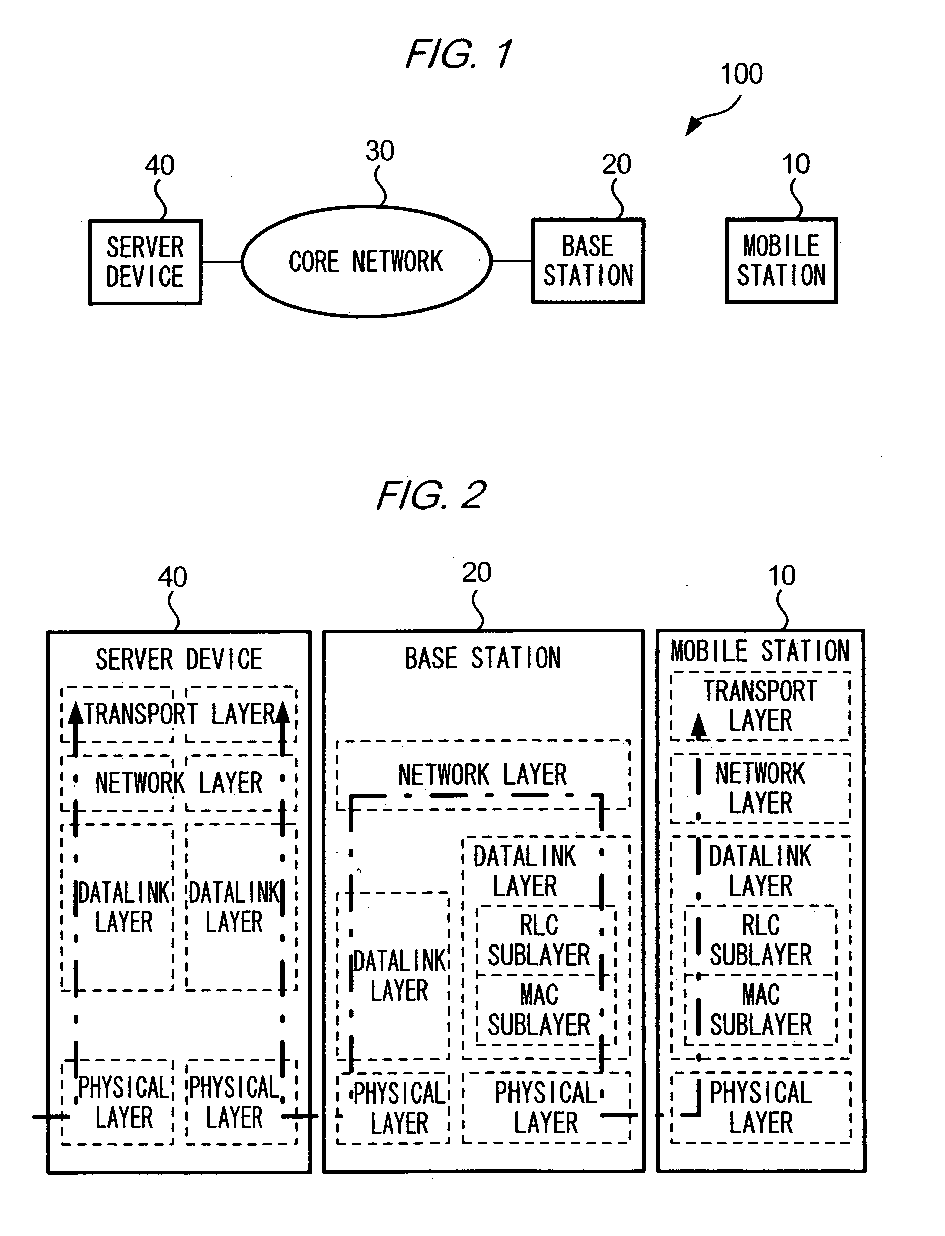
[0034]FIG. 1 is a diagram showing an example of a configuration of a communication system 100 according to an embodiment of the present invention.

[0035] As shown in the figure, a communication system 100 comprises a mobile station 10 carried by a user, a base station 20 capable of wirelessly communicating with mobile stations 10 located in a wireless area covered by base station 20, and a server device 40 connected to a core network 30 to which base station 20 is connected. Mobile station 10 is capable of communicating with server device 40 via base station 20 and core network 30. Server device 40 is a gateway server which is also connected to an external network (not shown) such as the Internet. Communication system 100 conforms to IMT-2000 (International Mobile Telecommunications-2000), and, within communication system 100, there can be one or more of...


PUM


Abstract

A CPU 41 of a server device 40 measures an elapsed time after transmitting a data segment, and suspends measuring time upon receiving an acknowledgement segment for the data segment. CPU 41 transmits a data segment whose elapsed time has reached a retransmission timeout value. CPU 41 sets, as a retransmission timeout value of a data block, a time value determined according to a monotonically increasing function of a number of transmissions of the data block, during a given time period after the second-time transmission of the data block, while CPU 41 sets a time value which is predetermined and is different from the time value determined by the monotonically increasing function during a period between the first-time transmission and immediately before the second-time transmission of the data block.

Description

[0001] This application claims priority under 35 U.S.C. § 119 to Japanese Patent Application Nos. 2004-016074 filed Jan. 23, 2004 and 2005-006824 filed Jan. 13, 2005, the entire contents of which are hereby incorporated herein by reference. BACKGROUND [0002] 1. Technical Field [0003] The present invention relates to a technique for improving transmission efficiency. [0004] 2. Background Information [0005] There are now in wide-spread use a transmitter device and a receiver device which perform data communication according to TCP (Transmission Control Protocol), a protocol followed in Transport Layer (Layer 4). When TCP is employed, a transmitter device sequentially detaches a portion of data having a predetermined data size from a data stream to be transmitted to a receiver device, appends to each data portion a header containing a sequence number to generate a data block (hereinafter, data segment), and transmits data segments starting from one having a least recent sequence number...

Claims


Application Information

Patent Timeline
Patent Type & Authority Applications(United States)
IPC IPC(8): H04L29/02H04L1/00H04L1/18H04L12/28H04L29/06
CPCH04L47/14H04L47/193H04L47/283H04W24/00H04W28/04H04L69/163H04L1/1825H04L1/188H04L12/5692H04L47/10H04L69/16H04W80/06H04W28/02H04W8/04
Inventor MIYAKE, MOTOHARUINAMURA, HIROSHIYAMAMOTO, KAZUNORISUZUKI, HIDEHARUTAKAHASHI, OSAMU
Owner NTT DOCOMO INC
Why Eureka
Try Eureka