Use of low-speed components in high-speed optical fiber transceivers

a technology of optical fiber transceivers and components, applied in the field of optical data communications, can solve the problems of high cost of 10 gbps optical transceivers and limit the achievable distance over installed optical fiber, and achieve the effects of cost reduction, cost reduction, and cost reduction

Inactive Publication Date: 2005-09-01
CLARIPHY COMM
View PDF64 Cites 81 Cited by
  • Summary
  • Abstract
  • Description
  • Claims
  • Application Information

AI Technical Summary

Benefits of technology

[0008] In another aspect, the presently disclosed invention provides a low-cost extended reach optical fiber link on embedded MMF, while providing significant cost reduction over existing 10 Gbps transceiver solutions. The system of this disclosure achieves significant cost reduction by realizing a 10 Gbps transceiver using lower performance optical and electronic components that are available at much lower cost than corresponding 10 Gbps components. Equalization is used to compensate for the distortion introduced by these components, as well as the distortion introduced by transport over distances of MMF exceeding 26 m, to include 220 m and 300 m of MMF. While MMF is the preferred medium described in this disclosure, the principles can be applied to enable the use of lower cost components when the medium is single mode fiber as well.

Problems solved by technology

Market barriers to widespread adoption of 10 Gbps networking include limitations on achievable distance over installed optical fiber and the high cost of 10 Gbps optical transceivers.

Method used


Image

  • Use of low-speed components in high-speed optical fiber transceivers
  • Use of low-speed components in high-speed optical fiber transceivers
  • Use of low-speed components in high-speed optical fiber transceivers

Examples


Embodiment Construction

[0023] Persons of ordinary skill in the art will realize that the following description is illustrative only and not in any way limiting. Other modifications and improvements will readily suggest themselves to such skilled persons having the benefit of this disclosure. In the following description, like reference numerals refer to like elements throughout.

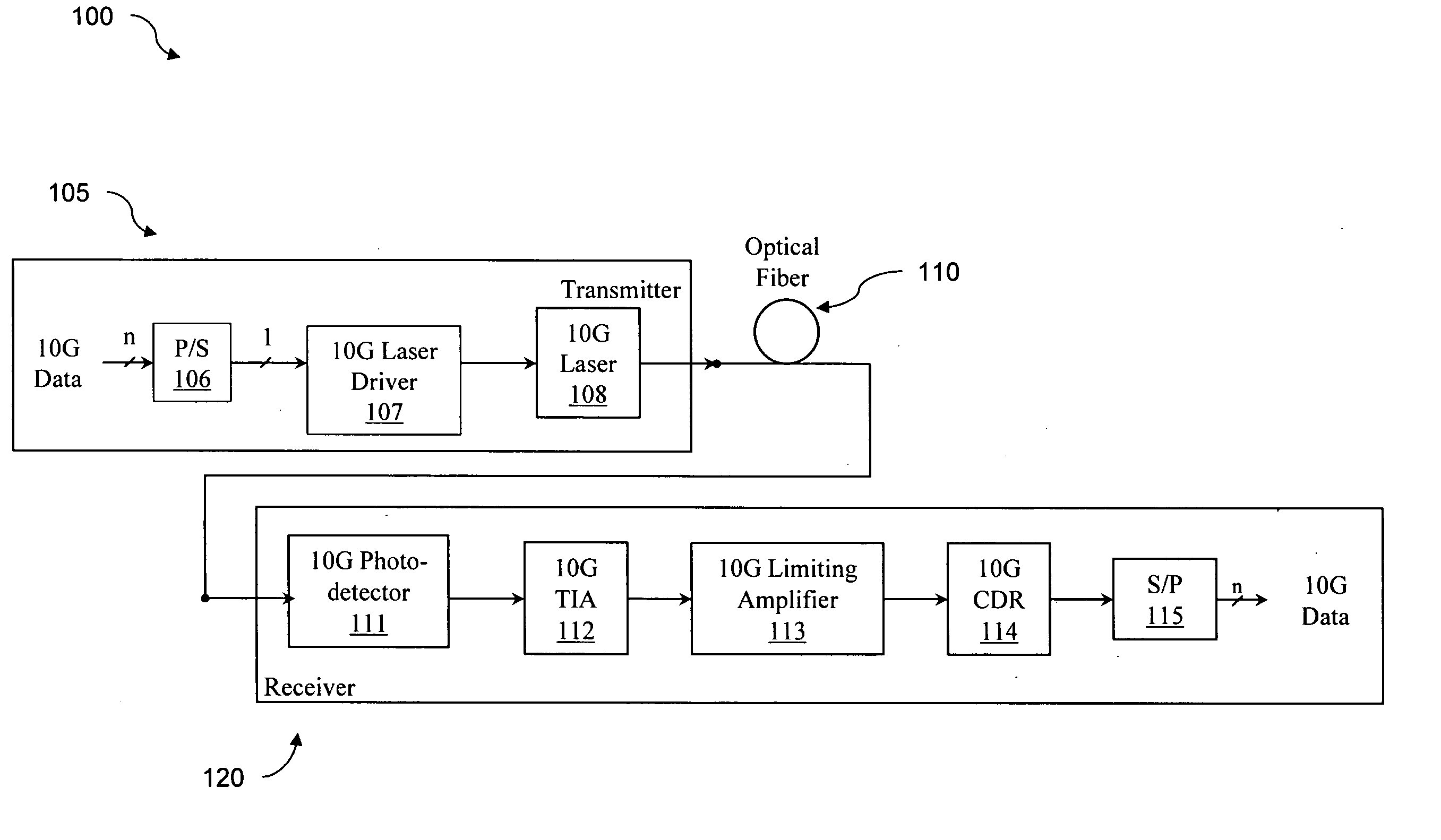
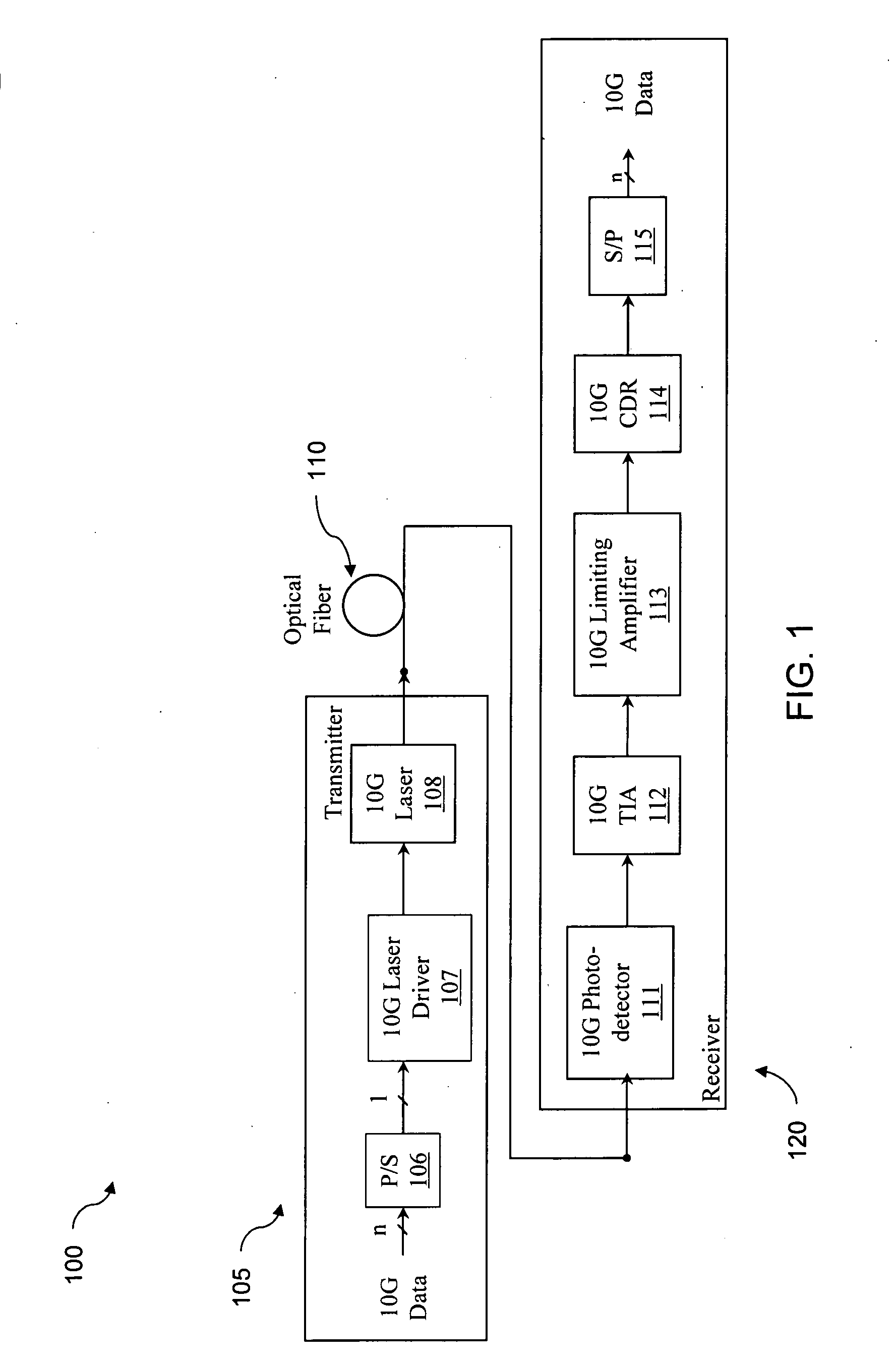
[0024] As used in this disclosure, 10 Gigabit (abbreviated as 10 G or 10 Gbps) systems are understood to include optical fiber communication systems that have data rates or line rates (i.e., bit rates including overhead) of approximately 10 Gigabits per second. The terms data rate and line rate will be used interchangeably, unless the context requires a distinction. These systems include, for example, 10 G Ethernet (10.31250 Gbps), 10 G Fibre Channel (10.51875 Gbps), SONET OC-192 (9.95328 Gbps), SONET OC-192 with FEC (10.70923 Gbps), and 10 G Ethernet with FEC (11.04911 Gbps and 11.09573 Gbps variants). The principles of the discl...


PUM


Abstract

An optical communication link is disclosed. In one embodiment, the link includes an optical transmitter including an electrical-to-optical converter for converting electrical signals into optical signals at the system data rate and launching said signals onto an extended length of optical fiber. The link also includes an optical receiver including an optical-to-electrical converter for converting received optical signals into electrical signals. In a preferred embodiment, either of the optical transmitter or optical receiver may include at least one low speed device designed to operate at a data rate less than the system data rate, and the receiver includes an equalizer coupled to the optical-to-electrical converter for compensating for signal distortions introduced by low speed devices.

Description

RELATED APPLICATIONS [0001] This application claims the priority date established by U.S. Provisional Application Ser. No. 60 / 536,148, filed on Jan. 12, 2004 and 60 / 541,674, filed on Feb. 2, 2004.BACKGROUND [0002] 1. Field of the Disclosure [0003] This application relates generally to optical data communications. [0004] 2. Background [0005] Optical fiber is widely used as a communications medium in very high speed digital networks, including local area networks (LANs), storage area networks (SANs), and wide area networks (WANs). The type of fiber used depends on the distances required and the cost sensitivity of the application. Recently, attention has been shifting towards 10 Gigabit systems. Market barriers to widespread adoption of 10 Gbps networking include limitations on achievable distance over installed optical fiber and the high cost of 10 Gbps optical transceivers. The invention described in this disclosure addresses both of these barriers. SUMMARY OF THE INVENTION [0006] I...

Claims


Application Information

Patent Timeline
Patent Type & Authority Applications(United States)
IPC IPC(8): H04B10/00H04B10/2581H04B10/43
CPCH04B10/2581
Inventor SWENSON, NORMANVOOIS, PAUL
Owner CLARIPHY COMM
Why Eureka
Try Eureka