Communication network

Inactive Publication Date: 2005-09-01
NOKIA SOLUTIONS & NETWORKS OY
View PDF6 Cites 43 Cited by
  • Summary
  • Abstract
  • Description
  • Claims
  • Application Information

AI Technical Summary

Benefits of technology

[0010] It is an aim of the embodiment of the present invention to improve th

Problems solved by technology

It is likely that at some point in the operational life of a communication network, that at least one of the elements is likely to fail resulting in unwanted downtime of the network.
In such a situation the c

Method used


Image

  • Communication network
  • Communication network
  • Communication network

Examples


Embodiment Construction

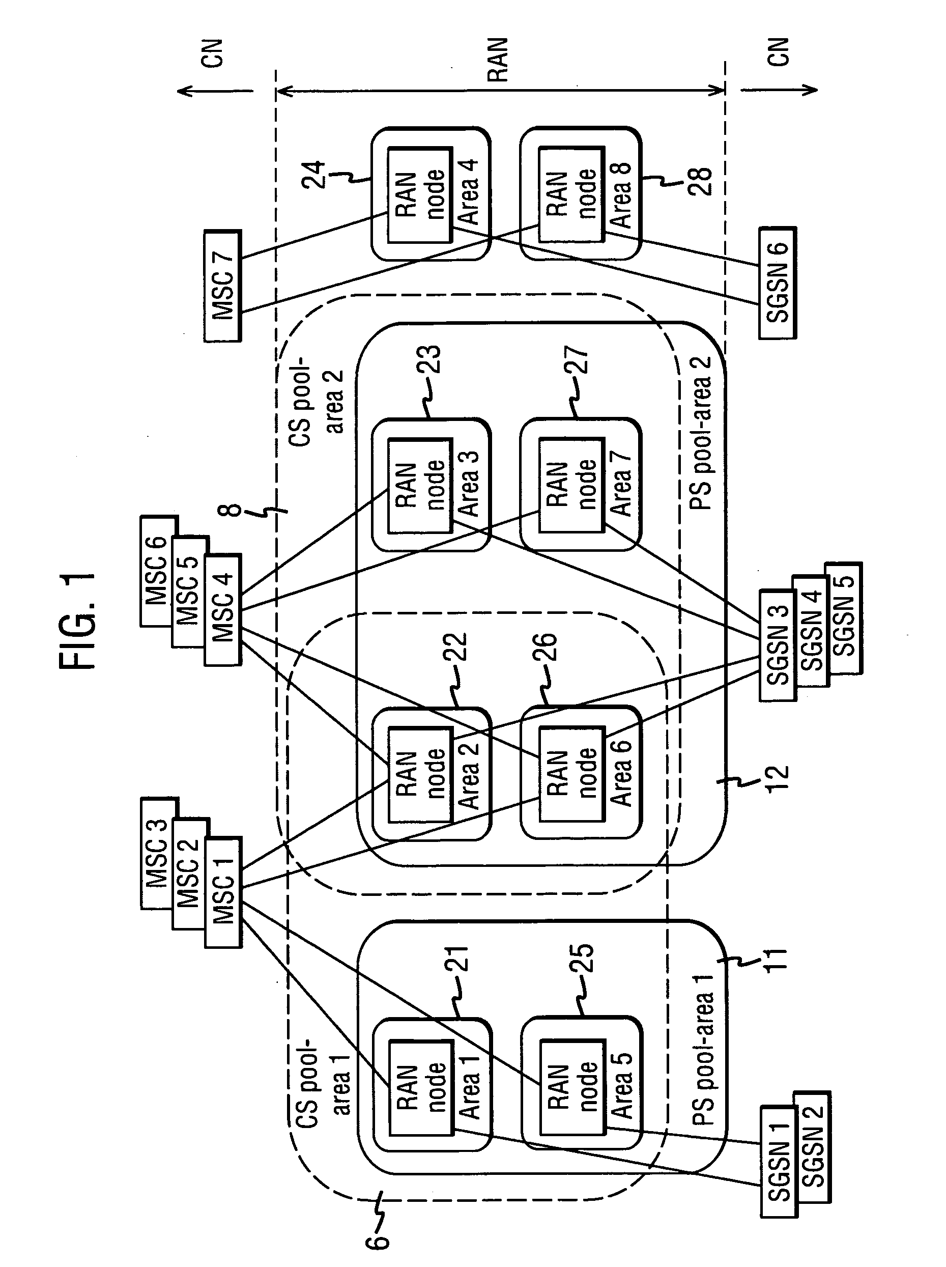
[0021] Various different pool areas are shown in FIG. 1, for example FIG. 1 shows four different pool areas 6, 8, 11, 12, wherein each pool area comprises a collection of one or more RAN node service areas 21-25. Furthermore, each pool area is served by multiple CN nodes in parallel which allow traffic to be shared in the pool area between each other. In FIG. 1, the CN nodes are MSC1-MSC7.

[0022] In other words pool areas may overlap which is not possible for MSC (CN) service areas. FIG. 1 shows a first circuit-switched (CS) pool area 6 which comprises the RAN node service areas 21, 22, 25 and 26 which are served by MSCs 1, 2 and 3. A second CS pool area 8 is shown as comprising RAN nodes 22, 23, 26 and 27 to be served by MSCs 4, 5 and 6. A first packet-switched (PS) pool area 11 is shown as comprising the RAN nodes 21 and 25 which are served by SGSNs 1, 2. Also, a second PS pool area 12 is shown which comprises RAN nodes 22, 23, 26 and 27 served by SGSNs 3, 4 and 5. It should be ap...


PUM


Abstract

A communication network is established by a connection to a user terminal that is capable of roaming amongst a plurality of serving areas. The network includes a controller for each serving area capable of routing a connection to a location covered by that serving area. If a controller serving the user terminal is faulty, a home database, which stores a plurality of identities of other controllers, is able to route the connection to the user terminal by selecting one of the other controllers that is valid.

Description

BACKGROUND OF THE INVENTION [0001] 1. Field of the Invention [0002] The present invention relates to a communication network for establishing a connection to a user terminal and in particular, but not exclusively, to a user terminal that is capable of roaming amongst a plurality of serving areas in a wireless communication network. [0003] 2. Description of the Related Art [0004] It is likely that at some point in the operational life of a communication network, that at least one of the elements is likely to fail resulting in unwanted downtime of the network. Therefore, network designers and telecommunication engineers are constantly striving to find mechanisms that will make a network more resilient to arbitrary failures. Broadly speaking, the elements of a wireless communication network are roughly grouped into being either radio access nodes (RAN) or core nodes (CN) as shown for example in FIG. 1. In practice, the core nodes could for example be MSC's (Mobile Switching Centres). [...

Claims


Application Information

Patent Timeline
IPC IPC(8): H04W24/02
CPCH04W24/04
Inventor BLOM, VESABACK, JUHANUMMINEN, RAILIJUUSOLA, VEIKKO
Owner NOKIA SOLUTIONS & NETWORKS OY
Why Eureka
Try Eureka