Pneumatic tire having a crown reinforcement structure with a plurality of adjacent cord reinforced strips and a process to manufacture or retread such a tire

a technology of crown reinforcement and pneumatic tires, which is applied in the field of pneumatic tires, can solve the problems of high degree of flexure in the crown area of pneumatic tires for high-speed applications, and the problem is particularly exacerbated, and achieve the effect of easy change in size and structur

Inactive Publication Date: 2005-09-08
THE GOODYEAR TIRE & RUBBER CO
View PDF14 Cites 21 Cited by
  • Summary
  • Abstract
  • Description
  • Claims
  • Application Information

AI Technical Summary

Benefits of technology

[0031] It is a further object of the invention, to provide a retreading process that can be carried out several times, for example 5 to 10 times, during the life cycle of the carcass without damaging it.
[0032] It is a further object of the invention, to provide a crown reinforcement structure that can be easily changed in size and structure according to the specific needs of the tire during the manufacturing process thus being adaptable to a wide range of sizes of tires.

Problems solved by technology

Pneumatic tires for high speed applications experience a high degree of flexure in the crown area of the tire as the tire enters and leaves the contact patch.
This problem is particularly exacerbated on aircraft tires wherein the tires can reach speed of over 200 mph at takeoff and landing.

Method used


Image

  • Pneumatic tire having a crown reinforcement structure with a plurality of adjacent cord reinforced strips and a process to manufacture or retread such a tire
  • Pneumatic tire having a crown reinforcement structure with a plurality of adjacent cord reinforced strips and a process to manufacture or retread such a tire
  • Pneumatic tire having a crown reinforcement structure with a plurality of adjacent cord reinforced strips and a process to manufacture or retread such a tire

Examples


Embodiment Construction

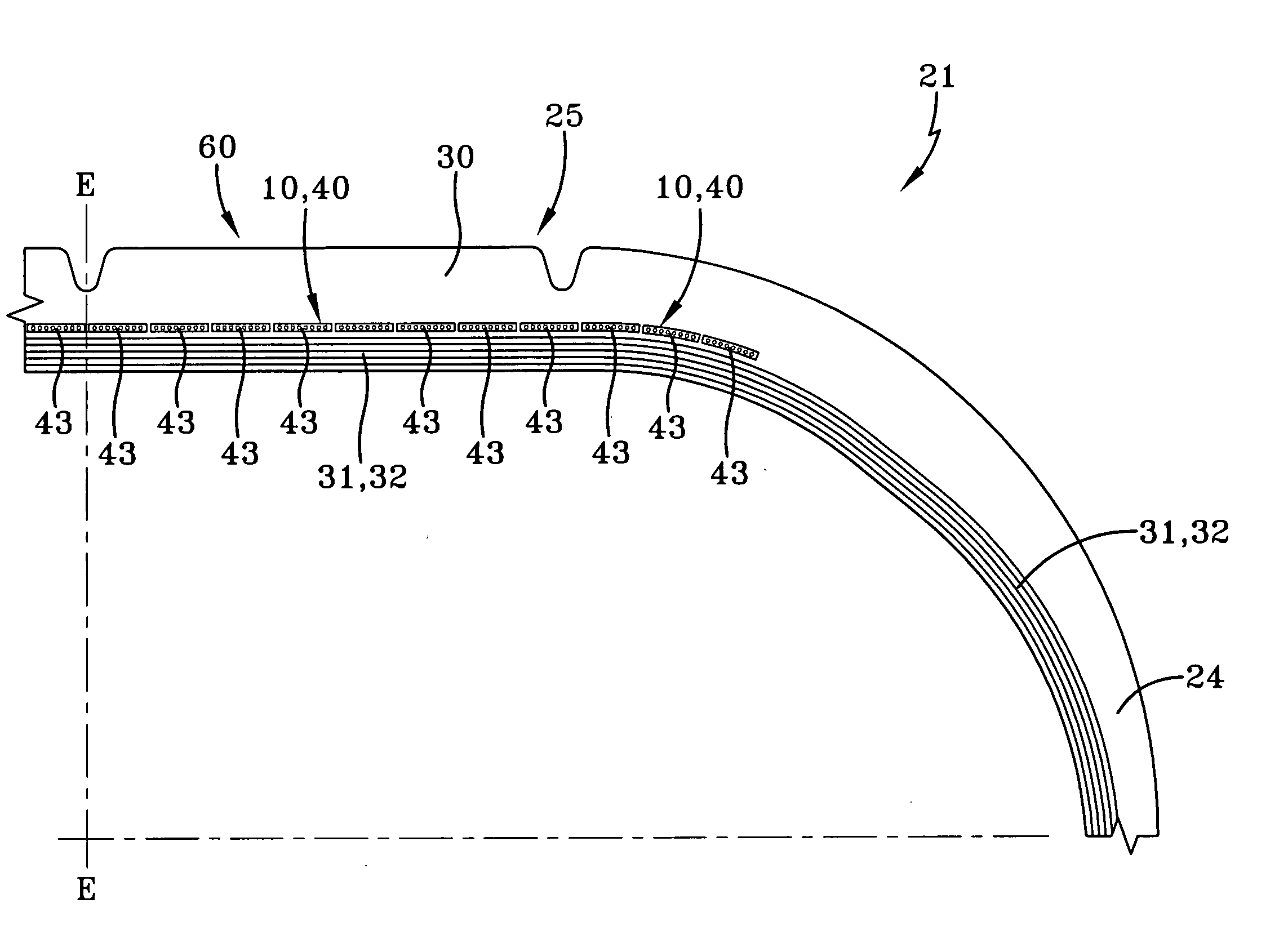
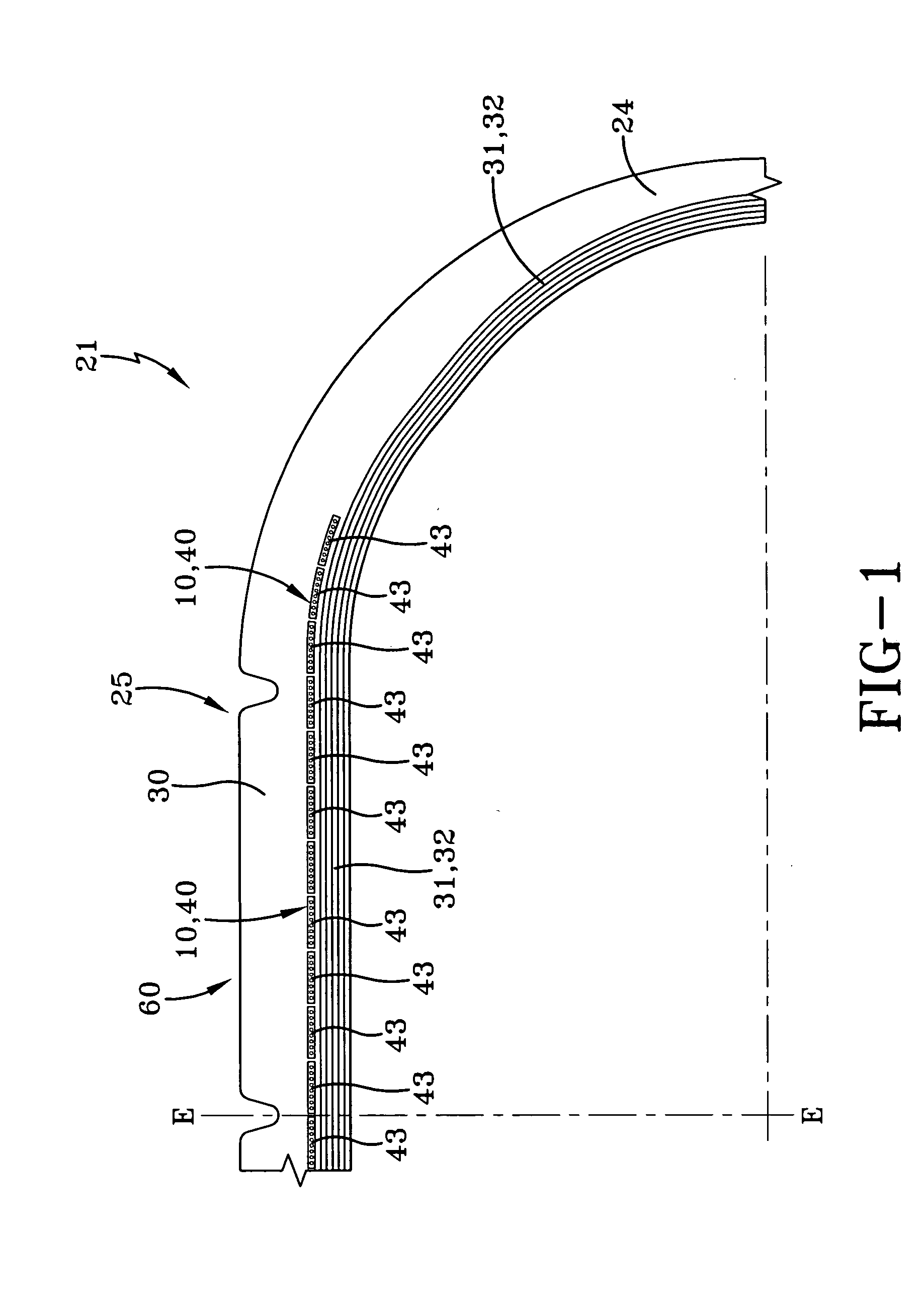
[0082]FIG. 1 shows a part of a tire 21, preferably a radial or bias aircraft tire, which comprises a pair of bead portions (not shown) each containing a bead core (not shown) embedded therein, a sidewall portion 24 extending substantially outward from each of the bead portions in the radial direction of the tire 21, and a tread portion 25 of substantially cylindrical shape extending between radially outer ends of these sidewall portions 24. Furthermore, the tire 21 comprises a carcass 31 toroidially extending from one of the bead portions to the other bead portion. The carcass 31 is comprised of at least one carcass ply 32, preferably a plurality of carcass plies 32. In one embodiment, among these carcass plies 32, four inner plies are wound around the bead core from inside of the tire toward outside thereof to form turnup portions, while two outer plies are extended downward to the bead core along the outside of the turnup portion of the inner carcass ply. Each of these carcass pli...


PUM

PropertyMeasurementUnit
widthaaaaaaaaaa
thicknessaaaaaaaaaa
distancesaaaaaaaaaa

Abstract

A pneumatic tire having a carcass and a crown region is disclosed, the crown region comprising a crown reinforcement structure and a tread portion with a radially inner side and a tread on its radially outer side. The crown reinforcement structure is located between the tread portion and the carcass and comprises a plurality of adjacent cord reinforced strips. The cord reinforced strips are in direct contact either with the inner side of the tread portion or are separated from the tread portion only by a rubber cushion layer. A process to manufacture such a tire comprises the steps of: (1) preparing an assembly with a carcass, a green tread reinforcing rubberized ply layer applied radially upside of the carcass, and a green tread portion applied onto the green tread reinforcing rubberized ply layer, and (2) transferring the assembly into the pneumatic tire by curing. The green ply layer is formed by winding a continuous green rubberized cord comprising strip radially upside onto the carcass or an intermediate layer applied onto the carcass. The green tread portion is applied in such a way onto the green tread reinforcing rubberized ply layer that it is either in direct contact with the green tread reinforcing rubberized ply layer or that it is separated from the green tread reinforcing rubberized ply layer only by a rubber cushion layer. Slightly modified, this process can also be used to retread a pneumatic tire, in particular an aircraft tire.

Description

FIELD OF THE INVENTION [0001] This invention relates to a pneumatic tire like a radial aircraft tire or bias aircraft tire having a crown reinforcement structure with a plurality of adjacent cord reinforced strips and processes to manufacture or retread such a tire. BACKGROUND OF THE INVENTION [0002] Pneumatic tires for high speed applications experience a high degree of flexure in the crown area of the tire as the tire enters and leaves the contact patch. This problem is particularly exacerbated on aircraft tires wherein the tires can reach speed of over 200 mph at takeoff and landing. When a tire spins at very high speeds the crown area tends to grow in dimension due to the high angular accelerations and velocity tending to pull the tread area radially outwardly. Counteracting these forces is the load of the vehicle, which is only supported in the small area of the tire known as the contact patch. [0003] U.S. Pat. No. 5,223,061 discloses a radial ply pneumatic tire, in particular ...

Claims


Application Information

Patent Timeline
Patent Type & Authority Applications(United States)
IPC IPC(8): B29D30/30B60C9/22B60C9/26
CPCB29D30/3028B29D30/54Y10T152/10783B60C9/26B60C9/2204B60C9/22
Inventor VERMAAT, PIETOOSTERWIJK, ANTONIUS JOHANNES BERNARDUSHARDING, ANTONY
Owner THE GOODYEAR TIRE & RUBBER CO
Why Eureka
Try Eureka