Printing member provided with identification means defined by or connectable to updateable means for recording data relative to the member and useful for its utilization

a technology of identification means and members, applied in the field of printing members, can solve the problems of increasing the danger of slippage, increasing the inertial mass, and requiring many printing sleeves, and achieve the effect of reducing the wastage of substrates

Active Publication Date: 2005-09-08
ROSSINI SPA
View PDF17 Cites 15 Cited by
  • Summary
  • Abstract
  • Description
  • Claims
  • Application Information

AI Technical Summary

Benefits of technology

[0016] Another object is to provide a printing member wherein even after numerous years of use of the printing member, these data or information remain specifically associated with that particular printing member and easily readable.
[0022] In accordance with an aspect of the present invention, the thickest portion of the activatable signaling device should be less than about one millimeter thick, which is measured in the radial direction when the transponder is positioned on one or more runs of resin-coated fiberglass. In this way, the presence of the activatable signaling device between even the first and second layers of the thin-walled sleeve does not result in any detectable degradation of the performance of the finished thin-walled sleeve. For example, there is no functionally appreciable degradation in the interference fit between the inner surface of the thin-walled sleeve and the exterior surface of the printing cylinder on which the sleeve becomes mounted during operation of the printing machine. Desirably, the thickest portion of the activatable signaling device should be less than about one half millimeter thick.
[0025] In accordance with a further aspect of the present invention, the activatable signaling device in the thin-walled sleeve provides the possibility of an improved method of effecting the desired registration of the sleeves on a gravure or flexographic printing machine for producing multi-color images on the substrate that is being printed. This improved method is accomplished by providing the printing machine with a positioning scanner and desirably a positioning scanner at each printing station. The positioning scanner is electronically connected to the controller of the printing machine. The positioning scanner detects the precise location of the microprocessor in the transponder and provides this information to the controller of the printing machine. Using this information, the printing machine can index the position of each sleeve so that all of the sleeves are in common registration to produce the desired image on the substrate that is being printed. In this way, all of the colors in the image are in proper registration from the very first image that is printed on the substrate by the machine. The improved method thereby eliminates the wastage of the substrate that occurs during manual registration with conventional sleeves.

Problems solved by technology

Most commercial printing machines have numerous printing cylinders and thus require numerous printing sleeves.
The thicker the sleeves then the greater the inertial mass of the rotating sleeve and the greater the danger of slippage if the interference fit should become compromised during the life of the sleeve.
Such treatments and operations can subject the sleeve to various expansions, compressions and twisting contortions.
However, as the sleeve is reused, the notch becomes wallowed out and cannot be reliably located relative to the pin on the mandrel.
Indeed, the pin of mandrel can be broken off with careless handling of the sleeves.
Each of these conditions of sleeve wear and pin damage renders the conventional manner of registration of the printing sleeve unacceptably inaccurate.
Users of the printing sleeve must rely on less efficient methods for achieving the same registration of the sleeve on the mandrel of the printing machine.
These less efficient methods can involve wastage of the underlying printing substrate during manual efforts to achieve the desired registration of the multiple color job on the substrate.

Method used


Image

  • Printing member provided with identification means defined by or connectable to updateable means for recording data relative to the member and useful for its utilization
  • Printing member provided with identification means defined by or connectable to updateable means for recording data relative to the member and useful for its utilization
  • Printing member provided with identification means defined by or connectable to updateable means for recording data relative to the member and useful for its utilization

Examples


Embodiment Construction

[0043] Reference now will be made in detail to the invention's presently preferred embodiments, which are illustrated in the accompanying drawings. Each example is provided by way of explanation of the invention, which is not restricted to the specifics of the examples. In fact, it will be apparent to those skilled in the art that various modifications and variations can be made in the present invention without departing from the scope or spirit of the invention. For instance, features illustrated or described as part of one embodiment, can be used on another embodiment to yield a still further embodiment. Thus, it is intended that the present invention cover such modifications and variations as come within the scope of the appended claims and their equivalents. The same numerals are assigned to the same components throughout the drawings and description.

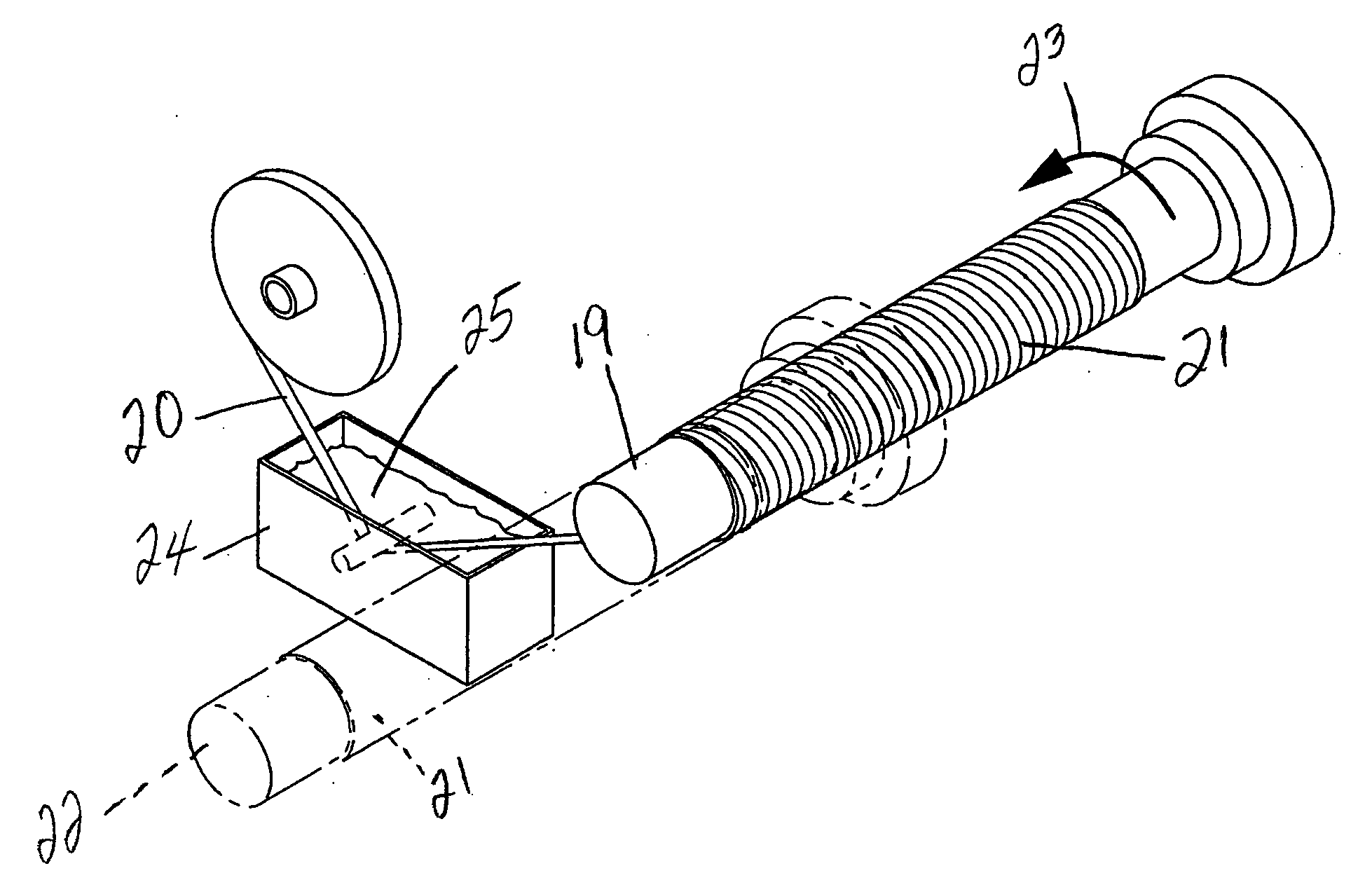
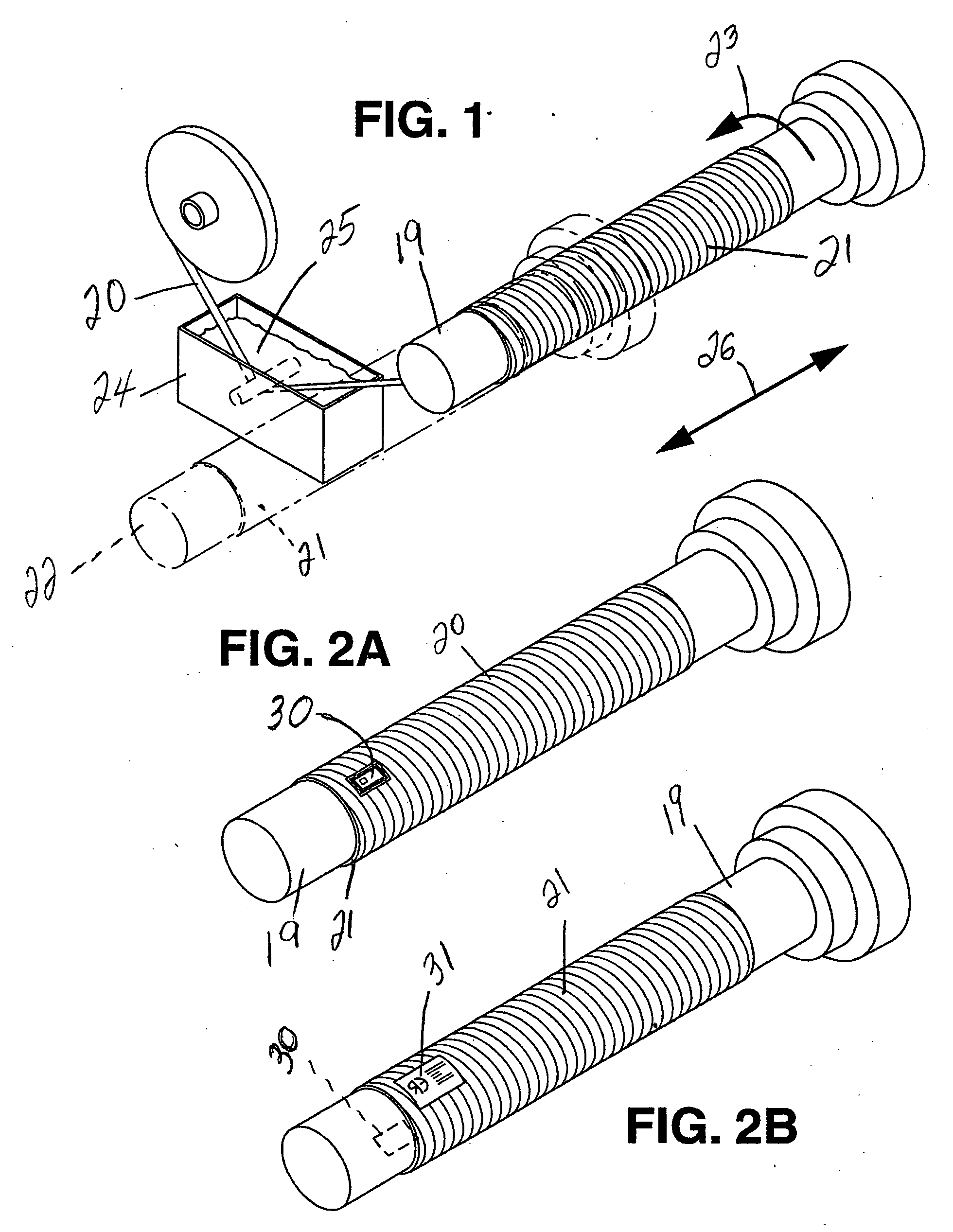
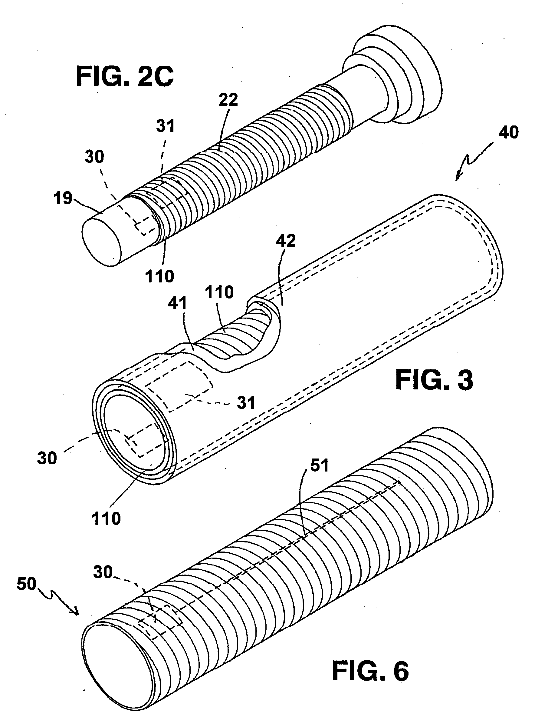
[0044] In general, one aspect of the present invention is directed to an improved method of making printing sleeves for use in fl...


PUM

PropertyMeasurementUnit
thicknessaaaaaaaaaa
temperaturesaaaaaaaaaa
thicknessaaaaaaaaaa

Abstract

A printing member such as a printing cylinder includes an at least partly metal cylinder, or a sleeve to be mounted on a mandrel rotating about its axis. The printing member comprises a body having a thickness. With the printing member there is associated an activatable signaling device that is connectable to a recording device that is arranged to store data related to at least one characteristic of the printing member or to the use of the printing member. The activatable signaling device can include a transponder such as an RFID.

Description

CROSS-REFERENCE TO RELATED APPLICATIONS [0001] The present application claims priority to currently pending Italian Patent Application number MI2004A000109, filed Jan. 27, 2004, and to U.S. Provisional Application Ser. No. 60 / 564,746 filed Apr. 23, 2004.STATEMENT REGARDING FEDERALLY SPONSORED RESEARCH OR DEVELOPMENT [0002] N / A BACKGROUND OF THE INVENTION [0003] The term “printing member” as used in the present document means any member for directly or indirectly transferring information onto a miscellaneous support by flexographic, copper-plate or offset printing. Consequently, a printing member comprises any one of the following elements: a printing cylinder in general such as a steel cylinder, a steel cylinder with chromium plated surface, a steel cylinder with rubber cladding, an aluminum cylinder with anodized or non-anodized surface; a printing sleeve to be mounted, in known manner such as by deformation with compressed air or by other means, on a mandrel (possibly of radially ...

Claims


Application Information

Patent Timeline
Patent Type & Authority Applications(United States)
IPC IPC(8): B41F13/08B41F33/00B41N1/00B41N7/00B65H81/00
CPCB29C53/64B29C53/8066B41F13/08B41F27/105B41N1/00B41N2207/04B41N7/00B41P2200/12B41P2200/30B41N2207/02B41N6/00
Inventor ROSSINI, FELICEBELL, MICHAEL
Owner ROSSINI SPA
Why Eureka
Try Eureka