Document feeder
a feeder and document technology, applied in the field of document feeders, can solve problems such as the complexity of the structure of the ad
- Summary
- Abstract
- Description
- Claims
- Application Information
AI Technical Summary
Benefits of technology
Problems solved by technology
Method used
Image
Examples
first embodiment
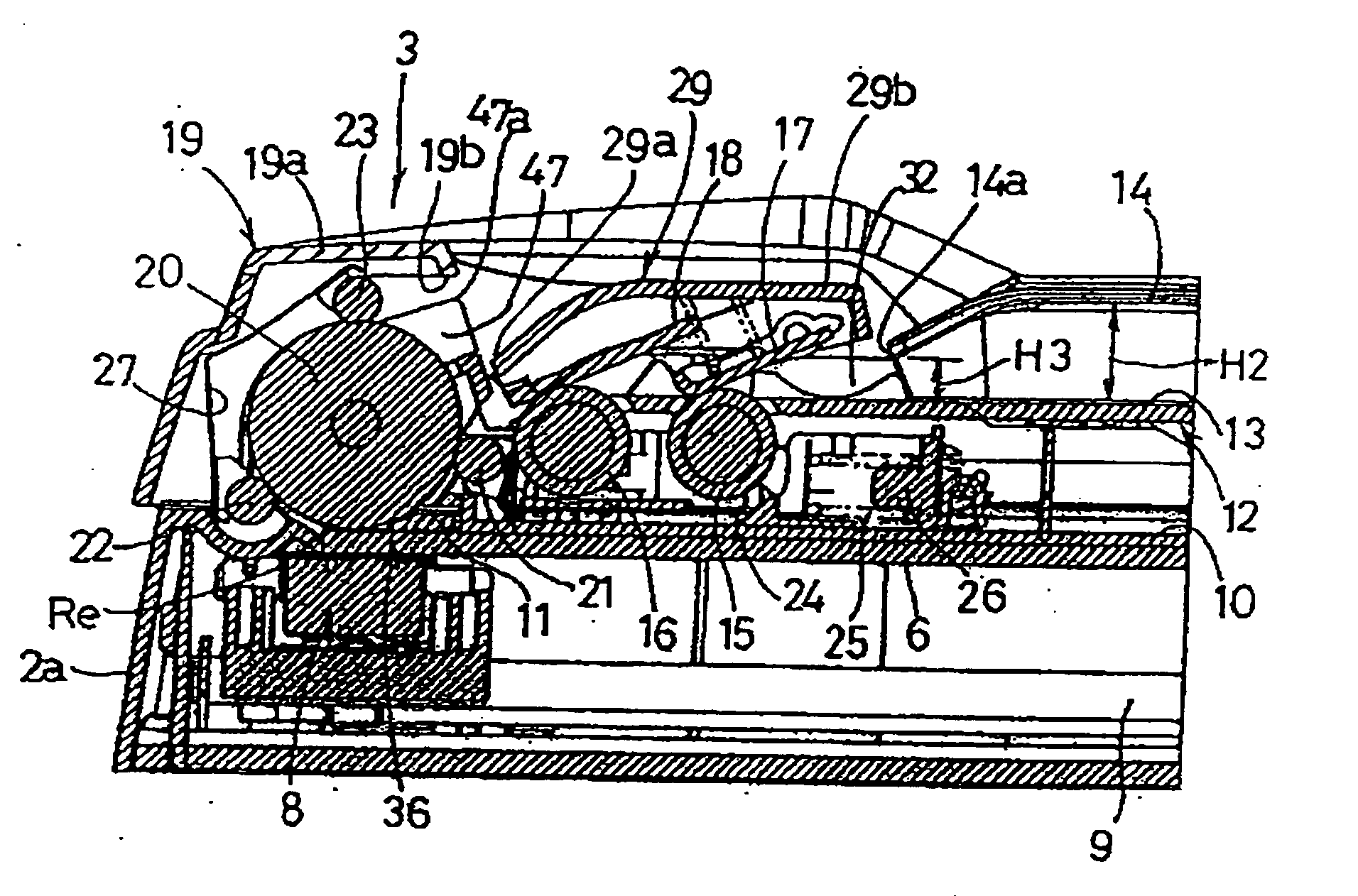
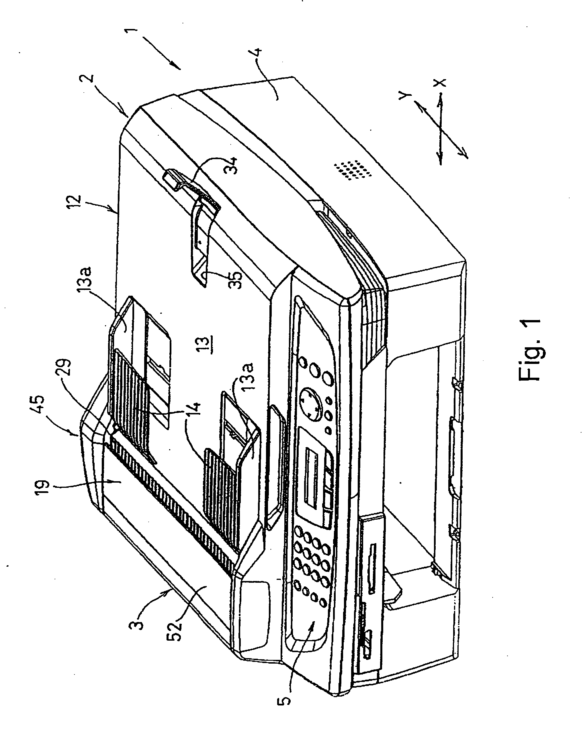
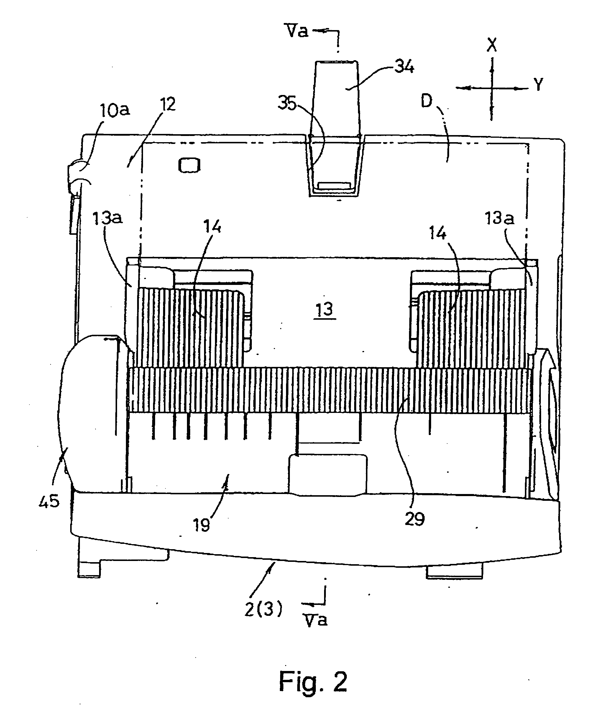
[0038] In the first embodiment, as shown in FIGS. 5-7 and 9, two rotation driving rollers (a pulling roller 15 and a separating roller 16, which are provided in this order from the upstream side with respect to the document conveying direction) functioning as the first rotation driving member and a reverse roller 20 with a large diameter functioning as the second rotation driving member are arranged substantially at a central portion of a direction perpendicular to the document conveying direction (i.e. the direction along the width of the document D), above the pressing plate 10 (referring to FIG. 12). The reading position Re linearly extends in a direction perpendicular to the document conveying direction. A rotation axis of a driving shaft 28 that supports the reverse roller 20 coincides with the reading position Re in the plan view. Thus, the lower surface of the peripheral surface of the reverse roller 20 faces the reading surface of the reading device 8 when the reading device...
second embodiment
[0052] A second embodiment for ensuring the above effect is shown in FIGS. 3, 4, 6, 7 and 13. A pair of engaging members 46 having a substantially semicylindrical shape in cross-section is disposed of the sides of the reverse roller 20 while sandwiching the reverse roller 20 therebetween, so as to extend in the width direction of the document D. Each of the engaging members 46 is disposed above each of the respective first pressing members 40 and continues to the upper part of each of the respective first pressing members 40. The pair of engaging members 46 covers the driving shaft 28 from the upper side. Each of the respective engaging members 46 is connected with each of the respective first pressing members 40 by an engaging device (not shown). A plurality of rib-shaped guiding members 47 is integrally formed on outer surfaces of the engaging members 46, at predetermined intervals, along the extension direction of the driving shaft 28. The guiding members 47 extend diagonally upw...
fourth embodiment
[0056] A fourth embodiment for maintaining the stacking order of the discharged documents D in the normal order is shown in FIG. 13. A plurality of sweeping rollers 51 is disposed at a substantially same height as the third pinch roller 23 located at the most downstream position in the document conveying direction. The sweeping rollers 51 can be a cylindrical roller with protrusions individually arranged on the periphery thereof at predetermined intervals, can be a roller having a spur-like cross section, or can be a spur made of a thin plate. The plurality of sweeping rollers 51 is arranged facing the outer surfaces of the engaging members 46 or the reverse roller 20. When the sweeping rollers 51 are disposed facing the outer surfaces of the engaging members 46, the sweeping rollers 51 are preferably willingly rotated. According to the structure of this embodiment, because of the rotation of the sweeping rollers 51, the front end of the document D that is released from the contact ...
PUM
 Abstract
Description
Claims
Application Information
 - R&D
- Intellectual Property
- Life Sciences
- Materials
- Tech Scout
- Unparalleled Data Quality
- Higher Quality Content
- 60% Fewer Hallucinations
Browse by: Latest US Patents, China's latest patents, Technical Efficacy Thesaurus, Application Domain, Technology Topic, Popular Technical Reports.
© 2025 PatSnap. All rights reserved.Legal|Privacy policy|Modern Slavery Act Transparency Statement|Sitemap|About US| Contact US: help@patsnap.com


