Rechargeable battery charging method and apparatus

a rechargeable battery and charging method technology, applied in electric vehicles, electric power, transportation and packaging, etc., can solve the problems of deteriorating performance, long time until charging is completed, and it is not possible to judge the state fully charged, etc., to achieve short time, high accuracy, and short time

Inactive Publication Date: 2005-09-08
SONY CORP
View PDF9 Cites 40 Cited by
  • Summary
  • Abstract
  • Description
  • Claims
  • Application Information

AI Technical Summary

Benefits of technology

[0029] In the above charging apparatus, the controller carries out the above described charging method according to an embodiment of the present invention using the charger and the voltage detector, and a lithium-ion based rechargeable battery can be charged in a short time.
[0030] According to the embodiment of the present invention, since the pulse charging is performed after charging is performed with the constant current until the terminal voltage becomes a fixed voltage (first set voltage) and whether or not the terminal voltage actually drops to the second set voltage or less is presumed based on a plurality of measurement results of both the elapsed time and the terminal voltage during the halt of charging in this pulse charging, such effectiveness that the lithium-ion based rechargeable battery can be charged in a short time is obtained.
[0031] Further, the terminal voltage Bn at the time when the elapsed time An from the start of the halt becomes the third set time which is longer than the second set time can be obtained by using the least-square method and by assuming that Bn is the linear expression of Cn, and furthermore whether or not the terminal voltage drops to the second set voltage or less can be presumed with high accuracy by the simple calculation, when the third set time is set to infinite time. Accordingly, such effectiveness that charging can be performed in a short time without incurring the deterioration in performance due to insufficient charging or overcharge can be obtained.
[0032] Moreover, since charging is ended not after the value of the terminal voltage Bn becomes higher than the second set voltage only once but after the calculated value of the terminal voltage Bn becomes higher than the second set voltage N times consecutively, the state fully charged can be judged with higher accuracy, so that such effectiveness that the performance of the rechargeable battery can further be improved is obtained.

Problems solved by technology

Therefore, when the lithium-ion battery is charged by such a method applied to the nickel-cadmium battery and the nickel-hydride battery, it is not possible to judge the state fully charged and insufficient charging or overcharge occurs, which makes the performance thereof deteriorate.
However, in the above method of performing the constant current charging followed by the constant voltage charging as described in (a), there has been such inconvenience that it takes long time until charging is completed.
In addition, there has also been such inconvenience that it takes long time until charging is completed in the method of the above described (b), because the halt time becomes long at the time of performing the intermittent charging (charging is continuously halted until the terminal voltage is stabilized).

Method used


Image

  • Rechargeable battery charging method and apparatus
  • Rechargeable battery charging method and apparatus
  • Rechargeable battery charging method and apparatus

Examples


Embodiment Construction

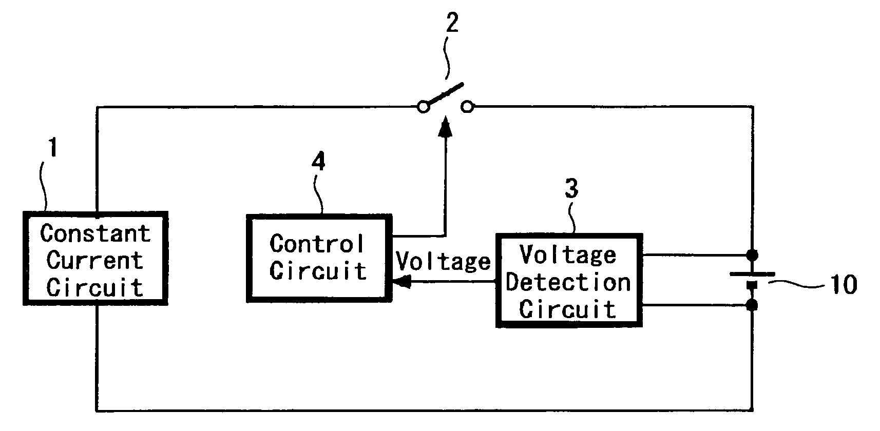
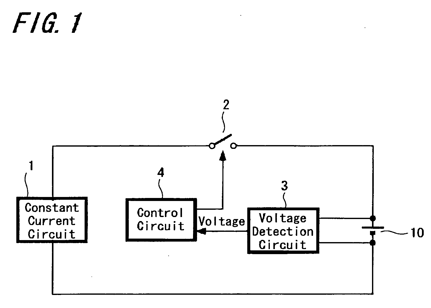
[0039] Hereinafter, the present invention is specifically explained using accompanied drawings. FIG. 1 is a block diagram showing a configuration of a charging apparatus to which this invention is applied. This charging apparatus is provided to charge a lithium-ion battery 10 of a full-charged voltage 4.2 (V) and a capacity 2,000 (mAh) and includes a constant current circuit 1, a switch 2, a voltage detection circuit 3 and a control circuit 4.

[0040] The constant current circuit 1 is a circuit to generate a constant current of 1.6 A based on electric power supplied from the outside (for example, commercial power).

[0041] The lithium-ion battery 10 to be charged is connected to the constant current circuit 1 through the switch 2. The switch 2 is controlled to be ON and OFF by the control circuit 4.

[0042] The voltage detection circuit 3 is a circuit to detect a terminal voltage of the lithium-ion battery 10. A detected output of the voltage detection circuit 3 is sent to the control ...


PUM


Abstract

A method and an apparatus for charging a lithium-ion based rechargeable battery in a short time is provided. A terminal voltage of the rechargeable battery is compared with a predetermined first set voltage V1 while charging the rechargeable battery with a constant current; pulse charging is performed in which charging is halted after the rechargeable battery is charged with the constant current only during a predetermined first set time T1 when the terminal voltage becomes the first set voltage V1 or more; both an elapsed time An from the start of the halt and a terminal voltage Bn at the elapsed time An are measured a plurality of times during the halt of charging in the pulse charging and the terminal voltage Bn is compared with a predetermined second set voltage V2; whether or not the terminal voltage drops to the second set voltage V2 or less is presumed based on measurement results of those elapsed time An and terminal voltage Bn in the case where the terminal voltage Bn is higher than the second set voltage V2 when the elapsed time An reaches a predetermined second set time T2; both the pulse charging and the presumption of the terminal voltage are repeated when presumed that the terminal voltage drops to the second set voltage V2 or less; and charging is ended when presumed that the terminal voltage does not drop to the second set voltage V2 or less.

Description

BACKGROUND OF THE INVENTION [0001] 1. Field of the Invention [0002] The present invention relates to a charging method and a charging apparatus suitable for charging a lithium-ion based rechargeable battery. [0003] 2. Description of the Related Art [0004] In recent years, a lithium-ion battery which is higher in energy density and lighter in weight than a nickel-cadmium battery and a nickel-hydride battery has been widespread as a rechargeable battery used for power supply to a notebook-size personal computer, a mobile phone unit and the like. [0005] Nickel-cadmium batteries and nickel-hydride batteries have such a characteristic that a terminal voltage slightly drops in a state fully charged. Accordingly, as a method for charging those batteries, there has been employed a method in which temporal change in terminal voltage is measured while charging the batteries with a constant current and the charging is finished by judging that the batteries are in full charge, when an amount of...

Claims


Application Information

Patent Timeline
Patent Type & Authority Applications(United States)
IPC IPC(8): H02J7/04H02J7/00
CPCH02J7/0073H02J7/0093H02J7/0086H02J7/0071H02J7/00711H02J7/007182H02J7/04
Inventor SANPEI, AKIRA
Owner SONY CORP
Why Eureka
Try Eureka