Output buffer providing multiple voltages

a technology of output buffer and voltage, applied in the direction of logic circuit, pulse technique, reliability increasing modifications, etc., can solve the problem of needing two power supplies

Active Publication Date: 2005-09-08
STMICROELECTRONICS PVT LTD
View PDF5 Cites 6 Cited by
  • Summary
  • Abstract
  • Description
  • Claims
  • Application Information

AI Technical Summary

Benefits of technology

[0013] Another object of the present invention is to provide an output buffer operating at a single supply voltage along with having a capability of being connected to a common node which may be driven to a higher voltage without current sinking.
[0014] Another object of the present invention is to provide an I / O buffer that achieves rail-to-rail swing at the output through bootstrapping.

Problems solved by technology

However, the disadvantage of this circuit is that it needs two power supplies to achieve the goal.

Method used


Image

  • Output buffer providing multiple voltages
  • Output buffer providing multiple voltages
  • Output buffer providing multiple voltages

Examples


Embodiment Construction

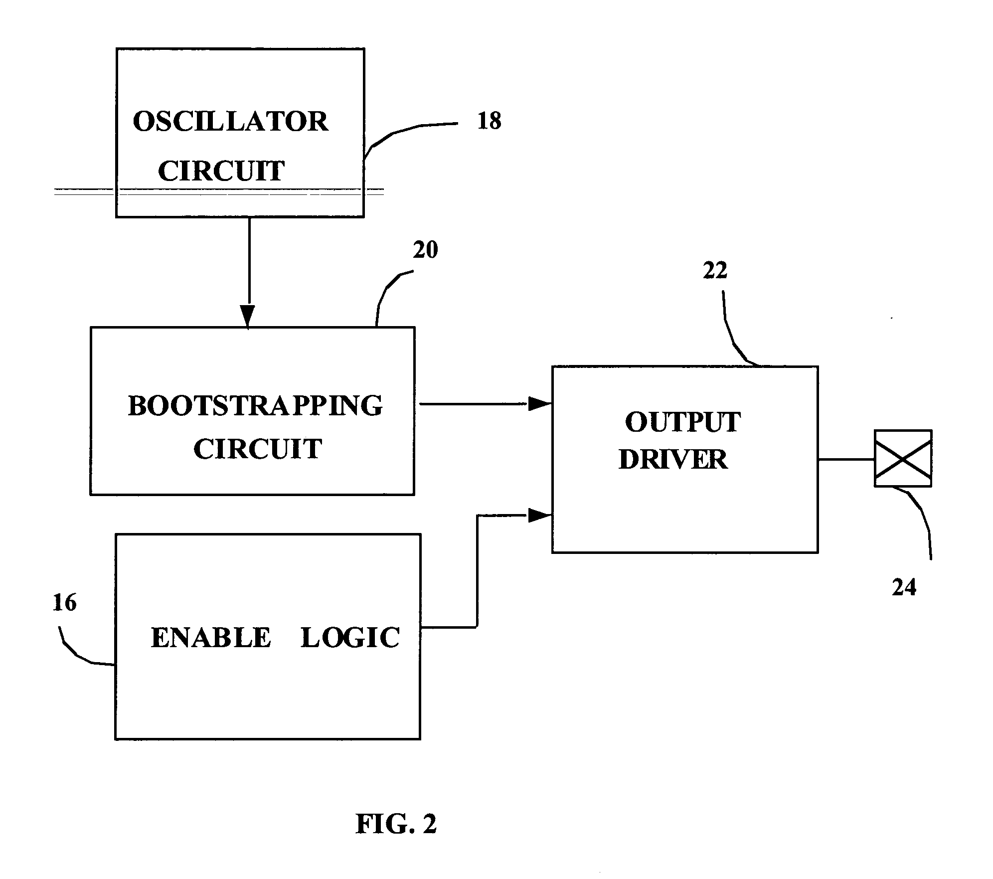
[0033]FIG. 2 illustrates a block diagram of the present invention. It contains an oscillator circuit 18 to provide continuous pulses to bootstrapping circuit 20. It also contains a logic enable circuit 16, which is used to drive the totem pole circuit 22.

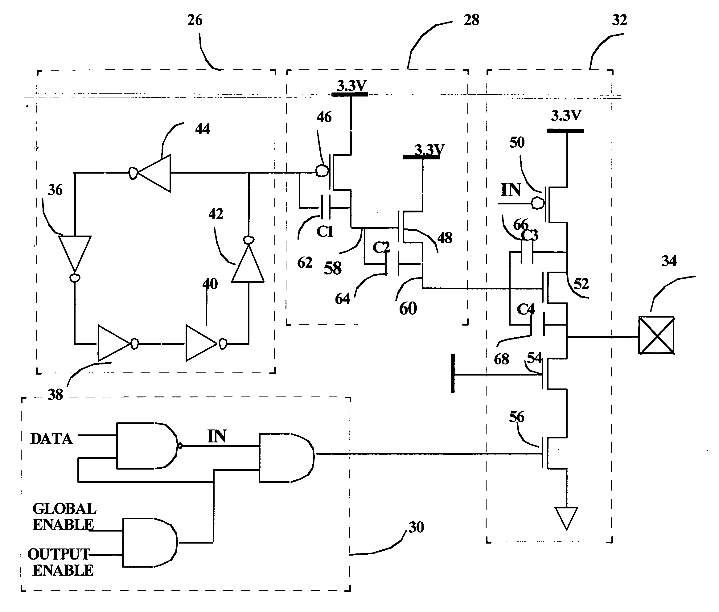
[0034]FIG. 3 illustrates a ring oscillator. It includes 5 inverters connected in a ring. The temperature and process variation don't affect the performance of the output buffer and the frequency of the oscillator is also immaterial as long as the bootstrap voltage does not go below a minimum level required for threshold drop compensation. Frequency of the oscillator is decided by the gain of the inverters (i.e. sizes of the inverters) and the number of stages. A minimum number of inverter stages are required to sustain oscillation. In the present invention, the number of stages is 5. The bootstrap voltage achieved should not exceed a certain level so that the circuit remains high-voltage tolerant.

[0035]FIG. 4 is a schematic diagra...


PUM


Abstract

The present invention provides an output buffer providing multiple voltages including an arrangement of bootstrapping capacitors, and a charge replenishing mechanism which provides continuous pulses to the arrangement of bootstrapping capacitors, thereby, maintaining voltage on the bootstrapping capacitors.

Description

BACKGROUND OF THE INVENTION [0001] 1. Field of the Invention [0002] The present invention relates to an output buffer providing multiple voltages at an I / O interface. More specifically, the present invention relates to an output buffer for driving an I / O pad at the desired high voltage level along with providing circuitry for tolerating higher voltages. [0003] 2. Discussion of the Related Art [0004] Implementation of integrated circuits using lower dimension feature sizes entails the need of scaling the supply voltages to a lower value. In certain applications, interfacing of circuits operating at different voltages is required. The output buffer of an I / O circuit uses a totem pole output for driving the pad. In a totem pole structure, the source of a P-channel device is connected to the supply voltage. Similarly, the source of an N-channel device is connected to the ground with the drain of both transistors connected together. Whenever a device operating at a lower voltage is conne...

Claims


Application Information

Patent Timeline
Patent Type & Authority Applications(United States)
IPC IPC(8): H03K19/0175
CPCH03K19/00315
Inventor DUBEY, HARI BILASH
Owner STMICROELECTRONICS PVT LTD
Why Eureka
Try Eureka