Ophthalmic apparatus

a technology of ophthalmoscope and ophthalmoscope, which is applied in the field of ophthalmoscope, can solve the problems of increasing the size of the apparatus and complicated apparatus, and achieve the effect of simple structur

Inactive Publication Date: 2005-09-08
NIDEK CO LTD
View PDF11 Cites 44 Cited by
  • Summary
  • Abstract
  • Description
  • Claims
  • Application Information

AI Technical Summary

Benefits of technology

[0006] The present invention has been made in view of the above circumstances and to provide an ophthalmic apparatus capable of projecting examination light after forming the light into a desired projection shape (pattern) by a simple structure.

Problems solved by technology

Such structure, however, would make the apparatus complicated.
The latter corneal shape measurement apparatus needs a structure to project the ring examination light; however, it would increase the apparatus in size.

Method used


Image

  • Ophthalmic apparatus
  • Ophthalmic apparatus
  • Ophthalmic apparatus

Examples


first embodiment

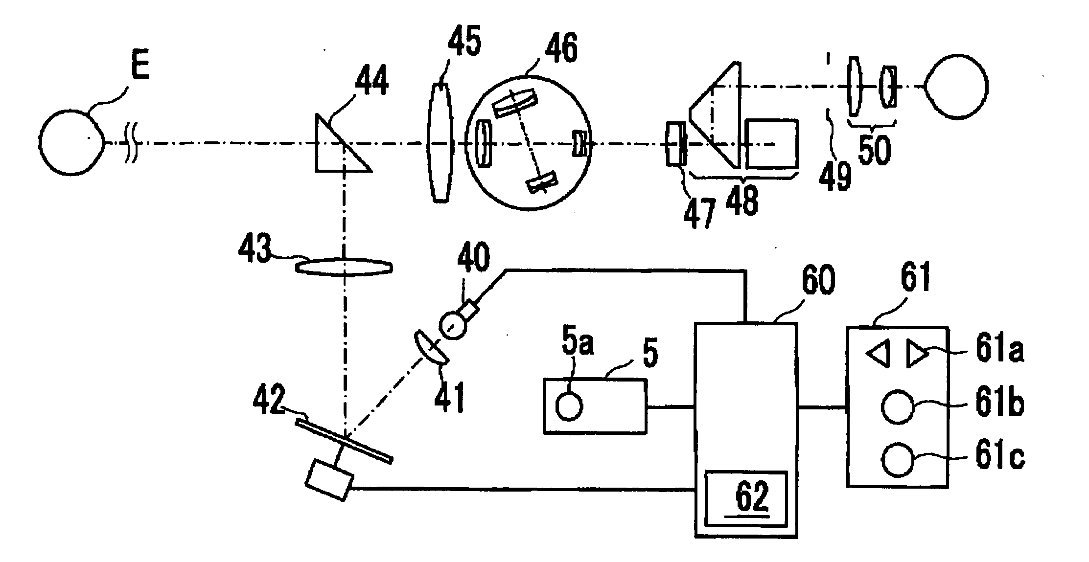
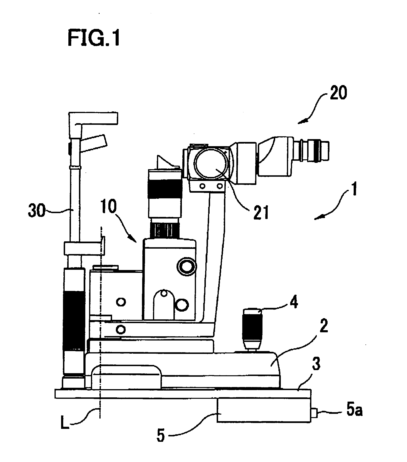
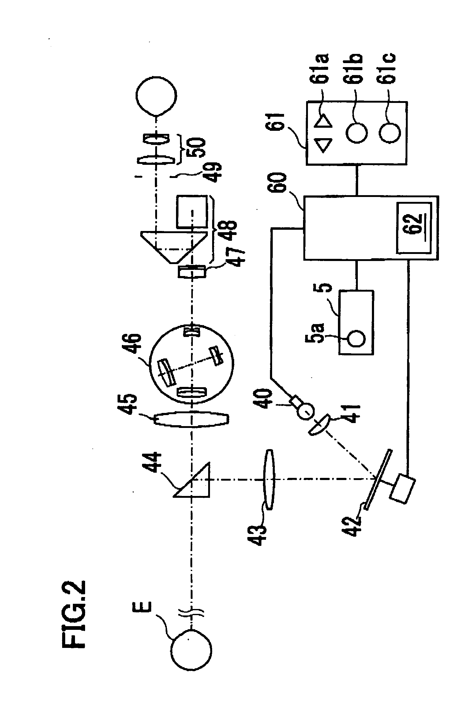
[0019]FIG. 1 is a schematic structural view of a slit lamp microscope (a slit lamp) in the invention. FIG. 2 is a schematic structural view of an optical system and a control system of the slit lamp.

[0020] A slit lamp main unit 1 has a base 2 at a bottom thereof. This base 2 is mounted on a table 3 so that the base 2 is movable horizontally on the table 3 by a well known moving mechanism including a joystick 4. Secured to the table 3 is a head rest 30 provided with a chin piece, a forehead rest, and others, for fixedly supporting the face (the head) of an examinee (a patient) in position.

[0021] A control box 5 is provided with a power switch not shown, a light-adjusting knob 5a for adjusting a light amount of examination light, and others.

[0022] A projection part 10 for projecting (irradiating) the examination light onto an eye of the examinee includes therein a light projecting optical system mentioned later. This projection part 10 is rotatable about an axis L with respect to th...

second embodiment

[0039]FIG. 4A is a schematic structural view of an optical system and a control system of a corneal shape measurement apparatus in the present invention.

[0040] The optical system for measuring a corneal shape of the examinee's eye E comprises a light projecting optical system including a light source 100 for examination (measurement), a micro mirror device 101, a lens 102, a beam splitter (a half mirror) 103, and a lens 104; and a light receiving optical system including the lens 104, the beam splitter 103, a lens 105, and a CCD camera 106 provided with an image pickup device which has the sensitivity to wavelengths in a visible to infrared range. Examination light emitted from the light source 100 is reflected along an optical axis L1 by deflected micro mirrors of the micro mirror device 101. The examination light reflected along the optical axis L1 passes through the lens 102, the beam splitter 103, and the lens 104 and then is projected onto the eye E. This apparatus is arranged ...

third embodiment

[0050]FIG. 5 is a schematic structural view of an optical system and a control system of a fundus shape measurement apparatus in the present invention. In FIG. 5, components or elements having the same functions as those in FIG. 4A are indicated by the same numerals and their explanations are omitted here.

[0051] A lens 200 is placed between the micro mirror device 101 and the beam splitter 103 to direct the examination light reflected along an optical axis L2 by the deflected micro mirrors the micro mirror device 101 toward the fundus of the eye E, forming an image of the examination light on the fundus. The lens 200 is movable along the optical axis L2 by a lens moving mechanism not shown for adjustment to a refractive power of the eye E.

[0052] Reflection light from the fundus is reflected by the beam splitter 103 and forms a spatial image at an image conjugate position through the lens 201. The light forming the spatial image passes through a black spot plate 202 having a small b...


PUM


Abstract

An ophthalmic apparatus for examining an eye of a patient, comprises: a light projecting optical system for projecting examination light onto the eye, the optical system including: a light source; and a projection shape forming device which is electrically controlled to change a reflecting area of a reflecting surface or a transmitting area of a transmitting surface and is arranged to reflect or transmit the examination light emitted from the light source while forming a projection shape of the examination light into a desired shape so that the examination light of the desired shape is projected onto the eye; and a selection unit for selecting the projection shape of the examination light; and a control part which drivingly controls the forming device based on the selected projection shape.

Description

BACKGROUND OF THE INVENTION [0001] 1. Field of the Invention [0002] The present invention relates to an ophthalmic apparatus for examining (including observing, measuring, and others) a patient's eye. [0003] 2. Description of Related Art [0004] There are ophthalmic apparatuses such as a slit lamp microscope (a slit lamp), a corneal shape measurement apparatus, and others, for examining (including observing, measuring, and others) a patient's eye. For example, the slit lamp is arranged to project (irradiate) examination light formed of a slit shape (pattern) onto the eye, and allow an examiner to observe a section of a cornea sectioned by the slit examination light through a microscope. The corneal shape measurement apparatus is arranged to project (irradiate) examination light formed of a ring shape (pattern) having a plurality of concentric rings onto the eye, photographing (picking up) a ring image formed on a cornea, and analyzing it to measure the shape of the cornea. [0005] The...

Claims


Application Information

Patent Timeline
Patent Type & Authority Applications(United States)
IPC IPC(8): A61B3/12A61B3/10A61B3/135
CPCA61B3/135
Inventor AKITA, JUNICHIKONDOH, NAOYUKISUMIYA, TOSHIFUMIOSHIMA, SUSUMUFUJISHIRO, AKIHIROMIZUNO, TOSHIAKI
Owner NIDEK CO LTD
Why Eureka
Try Eureka