

Anti-reflecting membrane, and display apparatus, optical storage medium and solar energy converting device having the same, and production method of the membrane
a technology of anti-reflecting membrane and production method, which is applied in the direction of optical elements, instruments, transportation and packaging, etc., can solve the problems of difficult to increase the physical strength of the thin aerogel membrane comprising the fine hollow particles of decreased shell thickness, difficult to increase the void fraction of these particles while increasing their thickness, and low mechanical strength. , to achieve the effect of preventing deposition, high physical strength and low refractive index
- Summary
- Abstract
- Description
- Claims
- Application Information
AI Technical Summary
Benefits of technology
Problems solved by technology
Method used
Image

Examples
example 1
[0188] First, the method for forming the anti-reflecting membrane on a glass plate is described.
(1) Pre-Treatment of Plate Before it is Coated With a Solution for Forming the Anti-Reflecting Membrane
[0189] A glass plate (100 by 100 by 1.1 mm in size, refractive index: 1.50) was irradiated with ultraviolet ray, 10 mW in intensity, emitted from a low-voltage mercury lamp for 5 minutes. This decreased contact angle of the plate surface with water from 30 to 35° to 10° or less.
(2) Preparation of Solution for Forming the Anti-Reflecting Membrane
[0190] A coating solution for forming the anti-reflecting membrane (hereinafter referred to as anti-reflecting membrane forming solution) was prepared by mixing 3 parts by weight of a silica sol solution (kept acidic with phosphoric acid, solvent: water / ethanol (1 / 4), containing an alkoxy silane polymer at 2.5% by weight) as a binder and 4 parts by weight of a silicon oxide dispersion for fine inorganic oxide particles (IPA-ST, Nissan Chemic...
example 2
[0198] An anti-reflecting membrane was formed in the same manner as in Example 1 (1) to (5), except that the glass plate was replaced by a single-crystalline sapphire plate (refractive index: 1.768).
[0199] The membrane was evaluated in the same manner as in Example 1 (6). It had a thickness of 120 nm and refractive index of 1.327.
[0200] The coated sapphire plate was measured for reflectance at a wavelength of 555 nm. It had a reflectance of below 0.3% versus 16% of the uncoated plate, confirming that the membrane exhibited the anti-reflecting capacity.
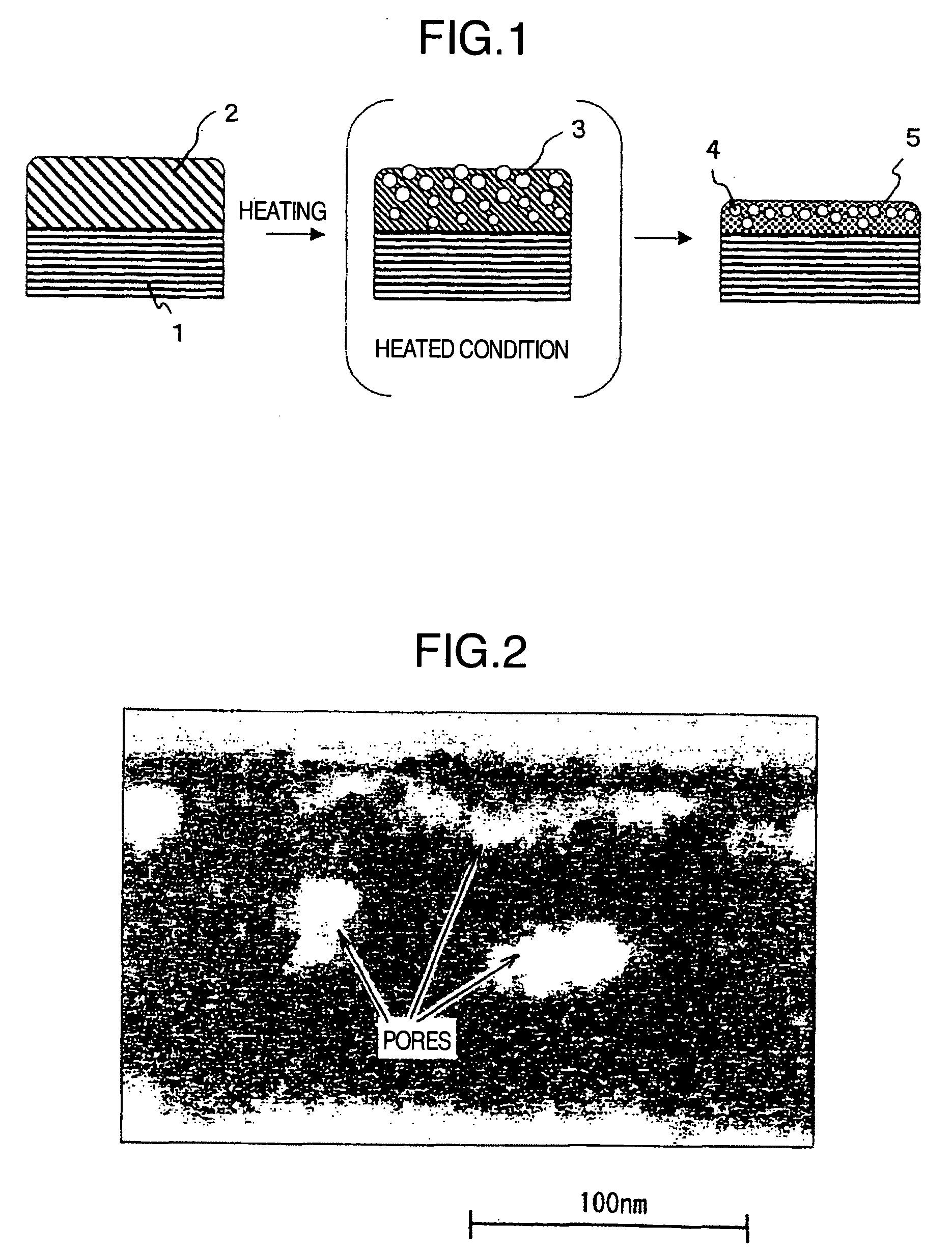
[0201] Pores of 5 to 150 nm in size were found in the cross-section of the membrane by a TEM, as was the case in Example 1.
[0202] The membrane had a surface resistance of 2×10¹⁰Ω at 20° C. and a relative humidity of 50%.
example 3
[0203] An anti-reflecting membrane was formed on a glass plate in the same manner as in Example 1 (1) to (5), except that 4 parts by weight of IPA-ST as a silicon oxide dispersion for preparation of anti-reflecting membrane forming solution was replaced by 4 parts by weight of IPA-ST-ZL (Nissan Chemical Industries), which is a dispersion of spherical colloidal silica as silicon oxide having a diameter of around 100 nm, containing solids at 30% by weight. The solution had a boiling point of 80° C.
[0204] The membrane was evaluated in the same manner as in Example 1 (6). It had a thickness of 190 nm and refractive index of 1.295.
[0205] The coated glass plate was measured for reflectance at a wavelength of 555 nm. It had a reflectance of 2.1% versus 8% of the uncoated plate, confirming that the membrane exhibited the anti-reflecting capacity.
[0206] Pores of 5 to 200 nm in size were found in the cross-section of the membrane by a TEM, as was the case in Example 1.
[0207] The membrane ...
PUM
| Property | Measurement | Unit |
|---|---|---|
| Percent by mass | aaaaa | aaaaa |
| Thickness | aaaaa | aaaaa |
| Thickness | aaaaa | aaaaa |
Abstract
Description
Claims
Application Information