DC power converter and method of operation for continuous conduction mode

a dc power converter and continuous conduction mode technology, applied in the direction of dc-dc conversion, power conversion systems, instruments, etc., can solve the problems of not necessarily optimal power density, capacitor co has a relatively large rating, and less than optimal power density, so as to reduce component rating requirements, improve power density, and reduce ripple ratings

Inactive Publication Date: 2005-09-08
NORTHEASTERN UNIV
View PDF12 Cites 34 Cited by
  • Summary
  • Abstract
  • Description
  • Claims
  • Application Information

AI Technical Summary

Benefits of technology

[0014] According to an advantage of the present invention, an inductor coupled to a switching full bridge operates in continuous conduction mode to improve power density, reduce component rating requirements, and provide a continuous output that reduces the demands for ripple ratings on the input and output components.
[0015] Other features and advantage of the present invention will become apparent from the following

Problems solved by technology

One difficulty with conventional current-fed DC-DC converters is that the energy provided from the input DC source to the load is discontinuous over the entire operating period.
Accordingly, a larger inductor is often used in the current-fed DC-DC converter, and power densities are not necessarily optimal.
Accordingly, capacitor Co has a relatively large rating, but less than optimal power density.

Method used


Image

  • DC power converter and method of operation for continuous conduction mode
  • DC power converter and method of operation for continuous conduction mode
  • DC power converter and method of operation for continuous conduction mode

Examples


Embodiment Construction

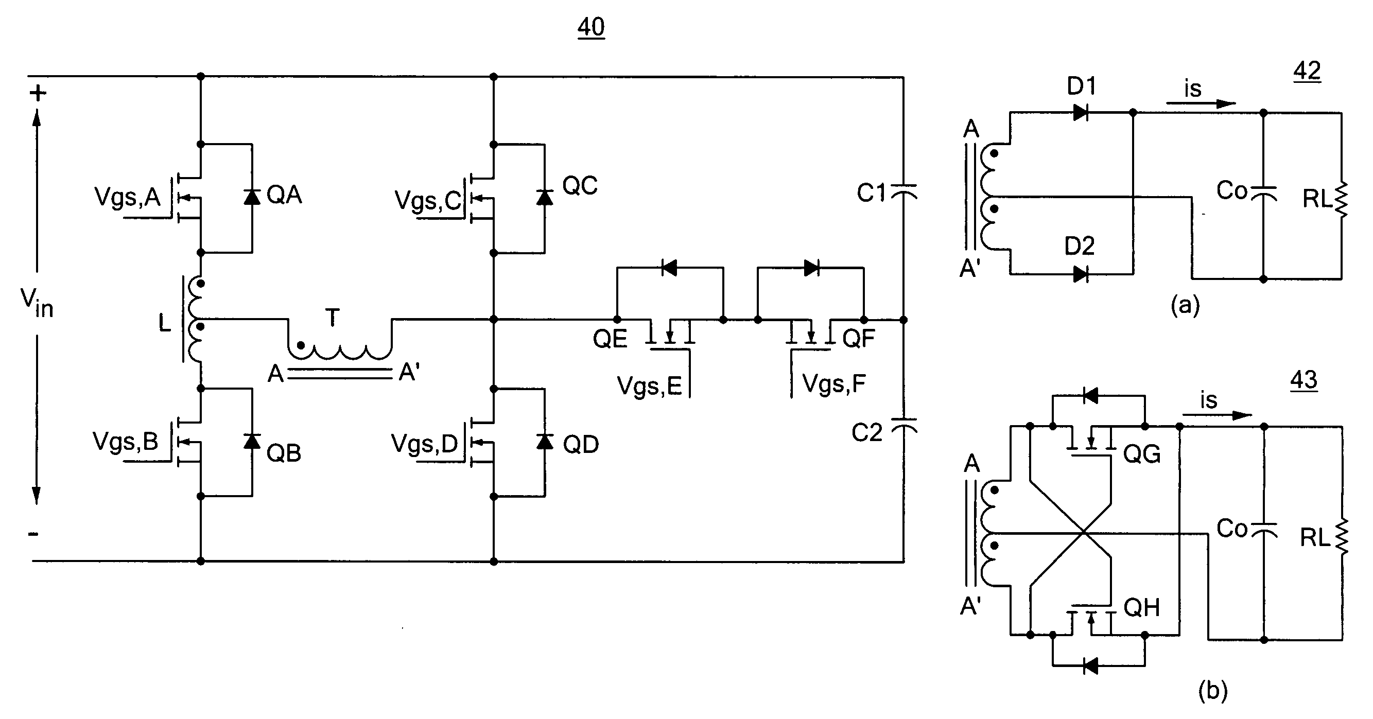
[0027] The present invention provides an isolated current-fed PWM DC-DC converter with a small inductance and no deadtime operation. In comparison to conventional current-fed DC-DC converters, the present invention reduces the inductance by a factor of 3.5 times. The reduction in inductance also produces a faster transient response time. The converter of the present invention can also provide an output stage with a simple self-driven synchronous rectification and a more continuous upward voltage, permitting a smaller rated output filter capacitance, while reducing the voltage stress on the power switches in the switching stage.

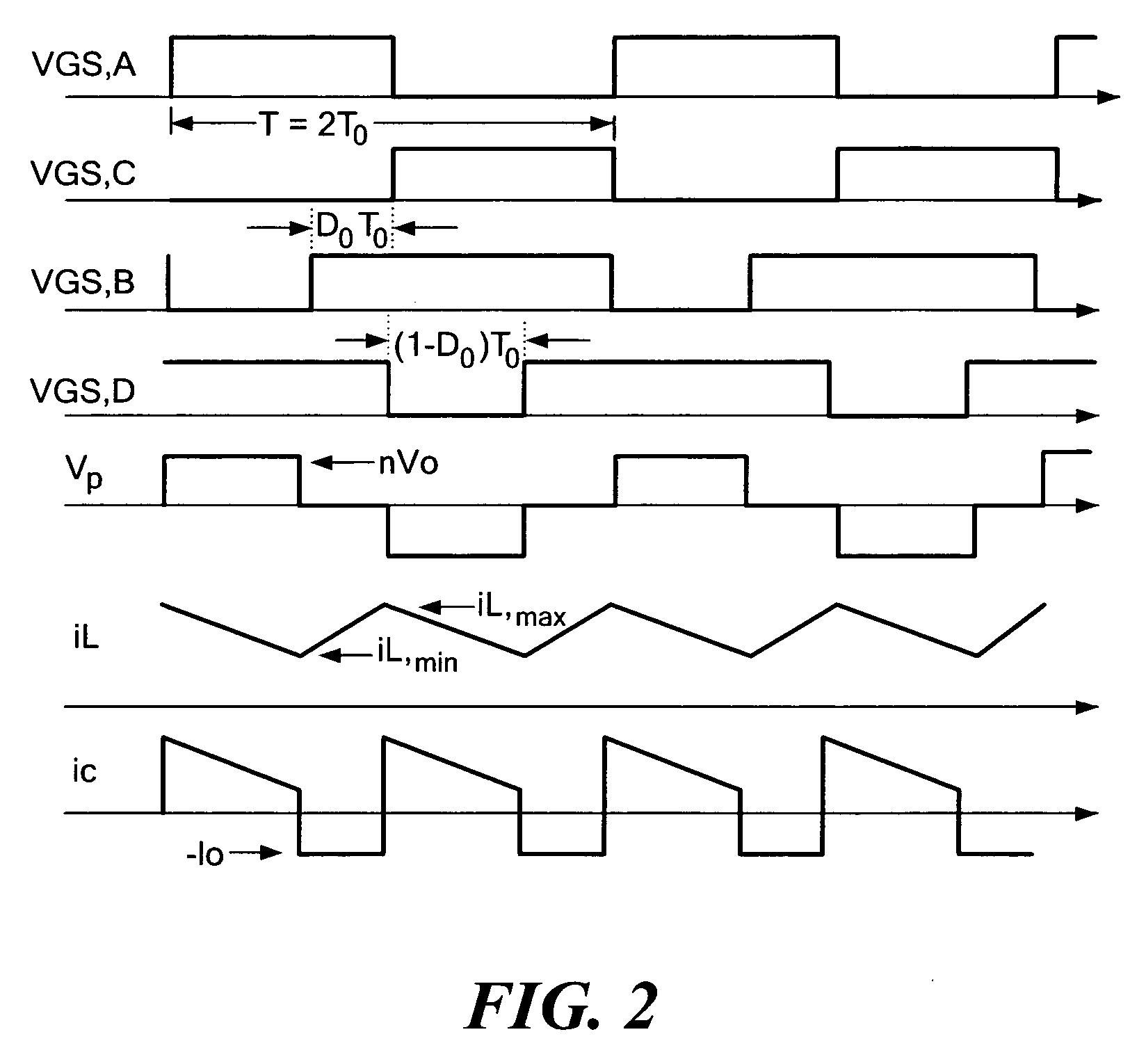
[0028] Operation of the converter according to the present invention provides an appearance of a current-fed full bridge converter in one stage and a current-fed half bridge in another stage. When operating in the current-fed half bridge stage, an inductor releases and sends stored energy to the load, together with energy supplied from a DC source. The input ...


PUM


Abstract

A current-fed DC-DC converter has a topology that improves converter performance and operates an input inductor in continuous conduction mode. The configuration and operation of the converter produces reduced requirements for circuit component ratings and leads to faster transient response time than conventional current-fed DC-DC converters. The converter can operate as an apparent current-fed full bridge converter in one stage, and an apparent current-fed half bridge converter in another stage. The input inductor is configured and operated to release stored energy to the load in conjunction with other energy storage components to provide a continuous output current that significantly reduces output voltage ripple, leading to reduced rating requirements and output components. The converter topology permits a portion of the switching stage to operate with no deadtime to further improve circuit responsiveness and efficiency.

Description

CROSS REFERENCE TO RELATED APPLICATIONS [0001] This application claims priority from U.S. Provisional Patent Application Ser. No. 60 / 546,719, filed Feb. 20, 2004, entitled ISOLATED CURRENT-FED PWM DDC-DC CONVERTER WITH SMALL INDUCTANCE AND NO DEADTIME OPERATION, the whole of which is incorporated herein.STATEMENT REGARDING FEDERALLY SPONSORED RESEARCH OR DEVELOPMENT [0002] N / A BACKGROUND OF THE INVENTION [0003] 1. Field of the Invention [0004] The present invention relates generally to PWM driven DC-DC converters, and relates more particularly to a current-fed isolated PWM DC-DC converter with reduced inductance and no deadtime. [0005] 2. Description of Related Art [0006] Current-fed DC-DC converters have recently seen a resurgence in the number of applications in which they are used. In general, the term “current-fed” in an isolated DC-DC converter refers to the fact that the filter inductor of the converter is on the primary side. The voltage and current of the primary winding of ...

Claims


Application Information

Patent Timeline
Patent Type & Authority Applications(United States)
IPC IPC(8): H02M3/335
CPCH02M2007/4811H02M3/33569H02M7/4811H02M3/33573H02M3/33571
Inventor LEHMAN, BRADLEY M.SONG, WEI
Owner NORTHEASTERN UNIV
Why Eureka
Try Eureka