Electric watch with radio communication function

a radio communication and electronic watch technology, applied in the field of electronic watch with radio communication function, can solve the problems of circuit board interference with signal reception, antenna cannot receive signals, and the control timepiece detracts from the appearance of the radio-controlled timepiece, so as to achieve more reliable signal transmission and reception, improve signal transmission and reception sensitivity of the antenna

Active Publication Date: 2005-09-08
SEIKO EPSON CORP
View PDF8 Cites 31 Cited by
  • Summary
  • Abstract
  • Description
  • Claims
  • Application Information

AI Technical Summary

Benefits of technology

[0010] Because the support substrate is made from a nonconductive and nonmagnetic material, the standard time signal travels through without interference from the support substrate. The antenna can therefore send and receive signals from the photoelectric generating means side even when the antenna is disposed to the photoelectric conversion unit opposite the surface of the cover member. Because the antenna can thus be housed inside the case member while maintaining good transmission and reception performance, the external appearance of the electronic timepiece with a radio communication function is improved.
[0058] While the case member of the secondary battery is normally metal, the secondary battery is located at a position far from the antenna because at least one of the gear train, switching unit, quartz oscillator unit, and control block is located between the antenna and battery. The secondary battery therefore does not interfere with the magnetic field of signals received by the antenna, the signal transmission and reception sensitivity of the antenna is improved, and more reliable signal transmission and reception is possible.

Problems solved by technology

However, locating the antenna externally to the case as with this radio-controlled timepiece detracts from the appearance of the radio-controlled timepiece.
As a result, there could be interference with signal reception by the antenna if the case is metal, for example, and poor signal reception could result in some situations.
However, because the solar cell circuit board is usually made from stainless steel or other metal, the circuit board interferes with signal reception, and the antenna cannot receive signals.
The back cover or case member of this radio-controlled timepiece, however, must be made from ceramic in order to lower the possibility of interference with signal reception, thus detracting from the appearance of the radio-controlled timepiece.
If the back cover or case member is made of metal in order to improve the appearance, signals cannot be received with good reception because the antenna is surrounded by the back cover and case member.

Method used


Image

  • Electric watch with radio communication function
  • Electric watch with radio communication function
  • Electric watch with radio communication function

Examples


first embodiment

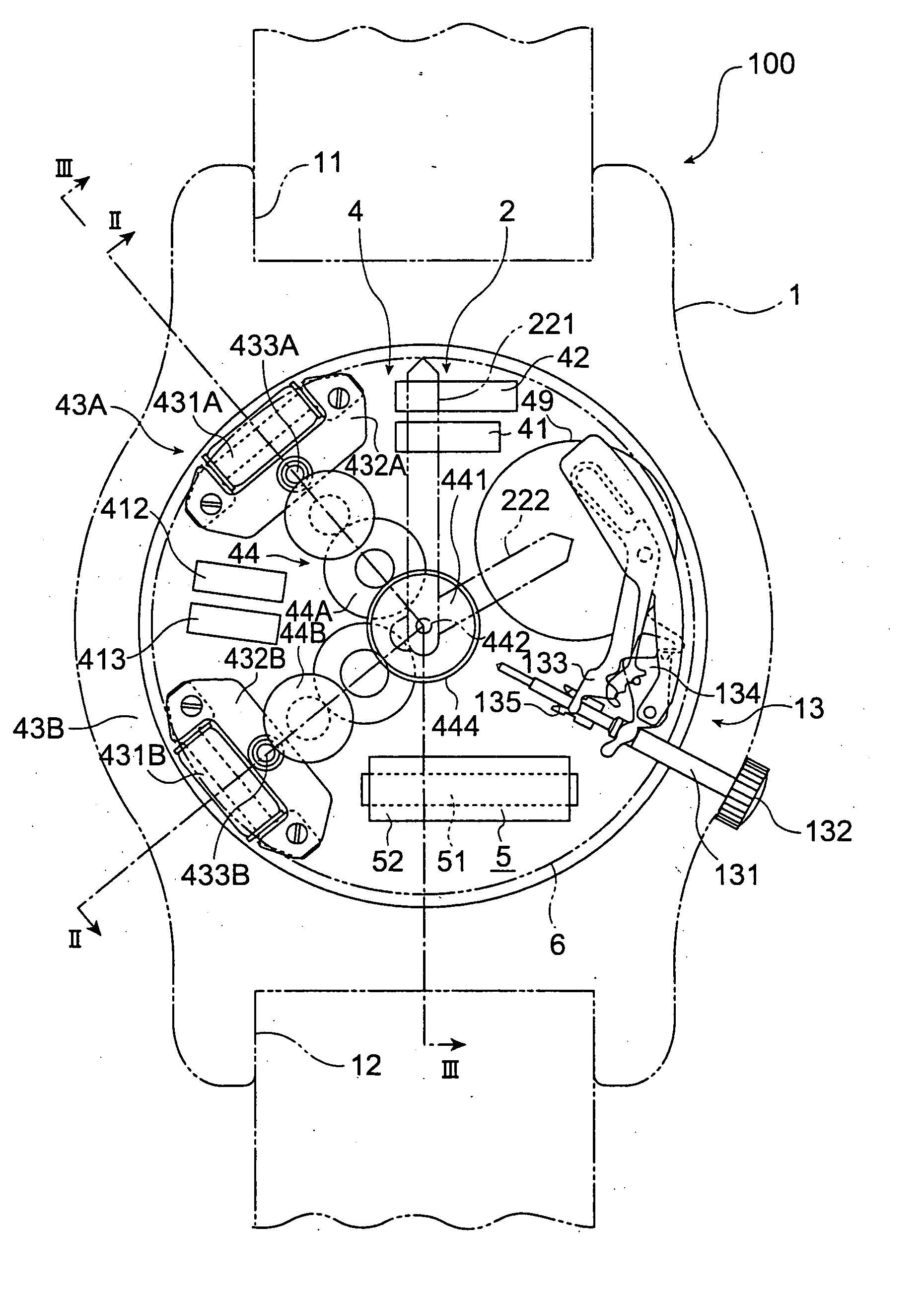
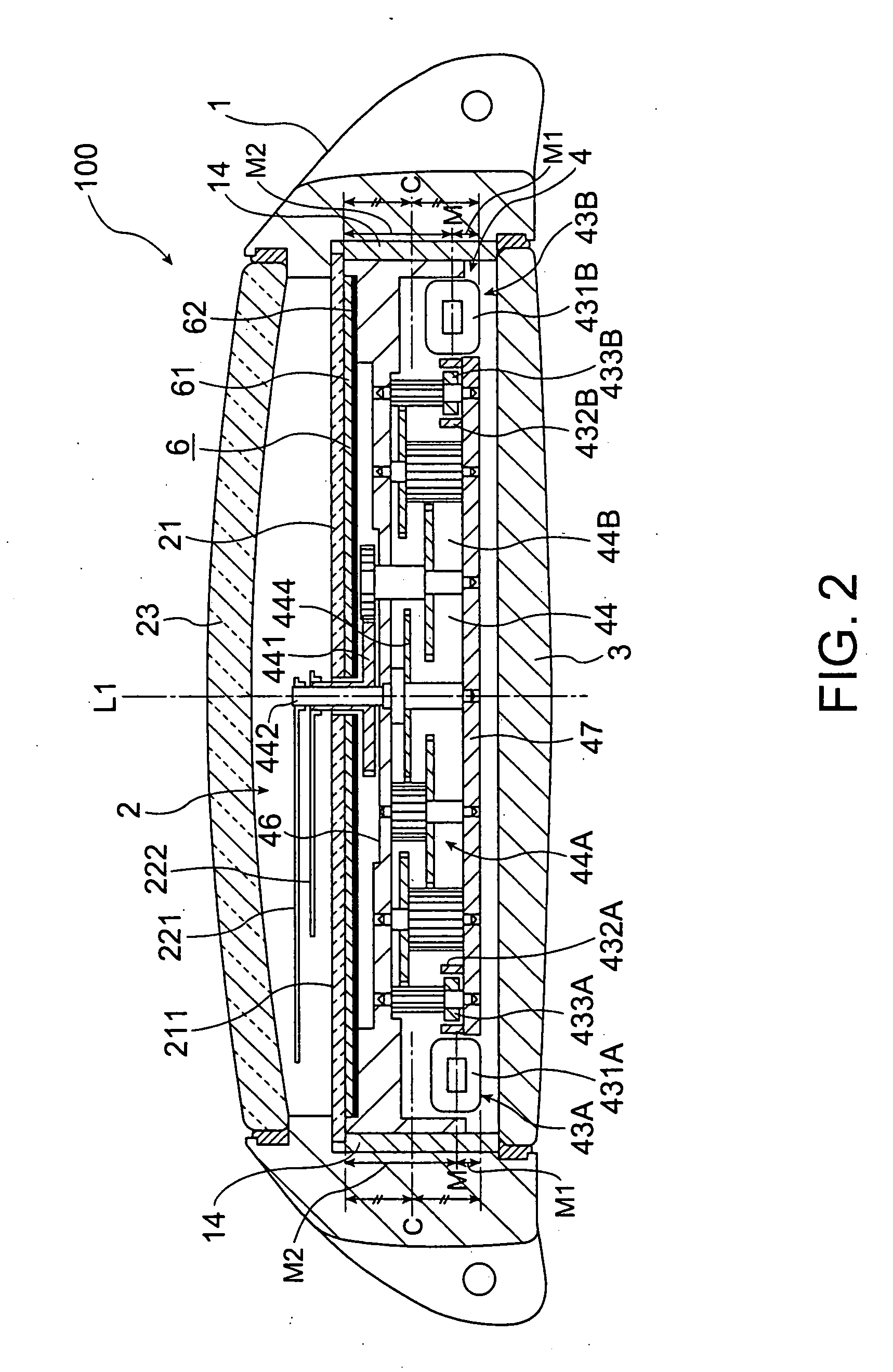
[0085]FIG. 1 is a plan view of a radio-controlled timepiece 100 as an electronic timepiece with a radio communication function according to a first embodiment of the present invention, FIG. 2 is a section view through line II-II in FIG. 1, and FIG. 3 is a section view through line III-III in FIG. 1.

[0086] This radio-controlled timepiece 100 is a wristwatch, and as shown in FIG. 1, FIG. 2, and FIG. 3 has a ring-shaped (a short cylindrical shape of which both ends are open) case member 1.

[0087] The case member 1 is a ring-shaped member of which both ends along the cylindrical axis L1 are open, cylindrical axis L1 being the axial direction of the gears that drive the hands (such as the axial direction of second wheel 444), and is made from metal such as brass, stainless steel, or titanium alloy. The thickness of the case member 1 is less than the diameter of the ring, and is preferably 10 mm or less or 5 mm or less. Lugs 11, 12 for attaching a wristwatch band are formed at mutually o...

second embodiment

[0141] A second embodiment of the present invention is described next. This second embodiment differs from the first embodiment in the arrangement of the photoelectric generating means 6 and antenna 5.

[0142]FIG. 5 is a plan view of a radio-controlled timepiece 100 according to a second embodiment of the invention, and FIG. 6 is a section view through line VI-VI in FIG. 5. As shown in FIG. 5 and FIG. 6, the photoelectric generating means 6 is a substantially circular disk with area approximately equal to the dial 21 and an approximately C-shaped notch 63 enclosing the antenna 5 is formed according to the shape of the antenna 5 at approximately 6:00. As a result, the antenna 5 and photoelectric generating means 6 are rendered so as to not overlap when the radio-controlled timepiece 100 is seen in plan view. The support substrate 62 is made from stainless steel or other conductive metal material. The material of the support substrate 62 could be a material that is magnetic, nonmagneti...

third embodiment

[0151] A third embodiment of the invention is described next. This third embodiment differs from the second embodiment in the configuration of the photoelectric generating means 6 and antenna 5.

[0152]FIG. 7 is a plan view of a radio-controlled timepiece 100 according to this third embodiment. As shown in FIG. 7, the photoelectric generating means 6 is divided into three portions (6A, 6B, 6C), and the photoelectric conversion elements 61A, 61B, 61C of these three photoelectric generating means 6A, 6B, 6C are connected in series to improve the electromotive force (voltage). As in the second embodiment, the support substrates 62A, 62B, 62C of these can be made from a conductive, high permeability magnetic material such as amorphous metal, permalloy, or stainless steel.

[0153] Photoelectric generating means 6B and 6C are rendered at approximately 4:00 and approximately 8:00 at positions corresponding to the ends of the antenna 5. These photoelectric generating means 6B and 6C are trian...


PUM


Abstract

A photoelectric generating means (6) is disposed proximally to the surface of the dial (21) on the back cover (3) side, and the dial (21) is made of a magnetic, optically transparent material. The support substrate (62) of the photoelectric generating means (6) is a nonmagnetic material, and the antenna (5) is located proximally to the surface of the support substrate (62) on the back cover (3) side. Because the support substrate (62) is a nonmagnetic material, external RF signals can pass through the dial (21) and photoelectric generating means (6) to the coil (52) of the antenna (5), and signals can thus be received by the antenna (5). Because the antenna (5) can be contained inside the case member (1), the appearance can be improved.

Description

BACKGROUND OF THE INVENTION [0001] 1. Field of the Invention [0002] The present invention relates an electronic timepiece with a radio communication function such as a radio-controlled timepiece, and relates more particularly to an electronic timepiece with a radio communication function having a photoelectric generating means for producing electricity by means of photoelectric conversion. [0003] 2. Description of Related Art [0004] Radio-controlled timepieces having an antenna to receive a radio signal containing standard time information and adjust the time based on the received time signal are one type of electronic timepiece with a radio communication function for receiving RF signals from external sources and transmitting RF signals to external devices. Radio-controlled timepieces that have the antenna disposed externally to the case so that the antenna can easily receive RF signals have been proposed (see, for example, Japanese Unexamined Patent Appl. Pub. H11-223684, FIG. 4)....

Claims


Application Information

Patent Timeline
Patent Type & Authority Applications(United States)
IPC IPC(8): G04C10/02G04G21/04G04G19/00G04G99/00G04R20/00G04R60/12H01Q1/27H01Q7/08
CPCG04C10/02G04R60/12H01Q7/08H01Q1/273G04G99/00
Inventor OGUCHI, ISAO
Owner SEIKO EPSON CORP
Why Eureka
Try Eureka