Standard time signal receiving time device and decoding method of time code signal

a time code and time signal technology, applied in the field of standard time signal receiving time device and decoding method of time code signal, can solve the problems of distorted waveform of the received and regenerated time code signal, inaccurate bit synchronization for detecting a rise starting point of the code pulse included in the time code signal, and poor signal receiving state of the radio wave, so as to achieve accurate decoding and simple arithmetic processing

Inactive Publication Date: 2005-09-08
LAPIS SEMICON CO LTD
View PDF4 Cites 47 Cited by
  • Summary
  • Abstract
  • Description
  • Claims
  • Application Information

AI Technical Summary

Benefits of technology

[0011] The present invention is made to solve such problems and provides a radio controlled clock and a decoding method of the time code signal in which the time code signal can be accurately decoded irrespective of the mixture of noises and the deterioration of a radio wave signal receiving situation, and the arithmetic processing is simple.

Problems solved by technology

However, in the real reception of the standard time signal, there is a fear that a noise signal is superposed on the receiving radio wave by sferics noises or generation noises from a device such as a car, a home electric appliance product, etc., and bit synchronization for detecting a rise starting point of the code pulse included in the time code signal becomes inaccurate.
Further, there is also a case in which the signal receiving state of the radio wave becomes worse by an arranging environment of the radio controlled clock and its signal receiving antenna and the pulse waveform of the received and regenerated time code signal is distorted.
However, in the prior art, for example, additional processing for sampling an integral value of the time code signal pulse generated on the basis of the standard time signal every predetermined time and discriminating the code, etc. is performed and its arithmetic calculation becomes complicated so that the calculating amount tends to be increased.
Therefore, a computer having large processing ability is required in the radio controlled clock taking the fault countermeasure.
Further, since it is necessary to perform the increased arithmetic processing by a high speed clock, product cost is raised and electric power consumption is increased.

Method used


Image

  • Standard time signal receiving time device and decoding method of time code signal
  • Standard time signal receiving time device and decoding method of time code signal
  • Standard time signal receiving time device and decoding method of time code signal

Examples


first embodiment

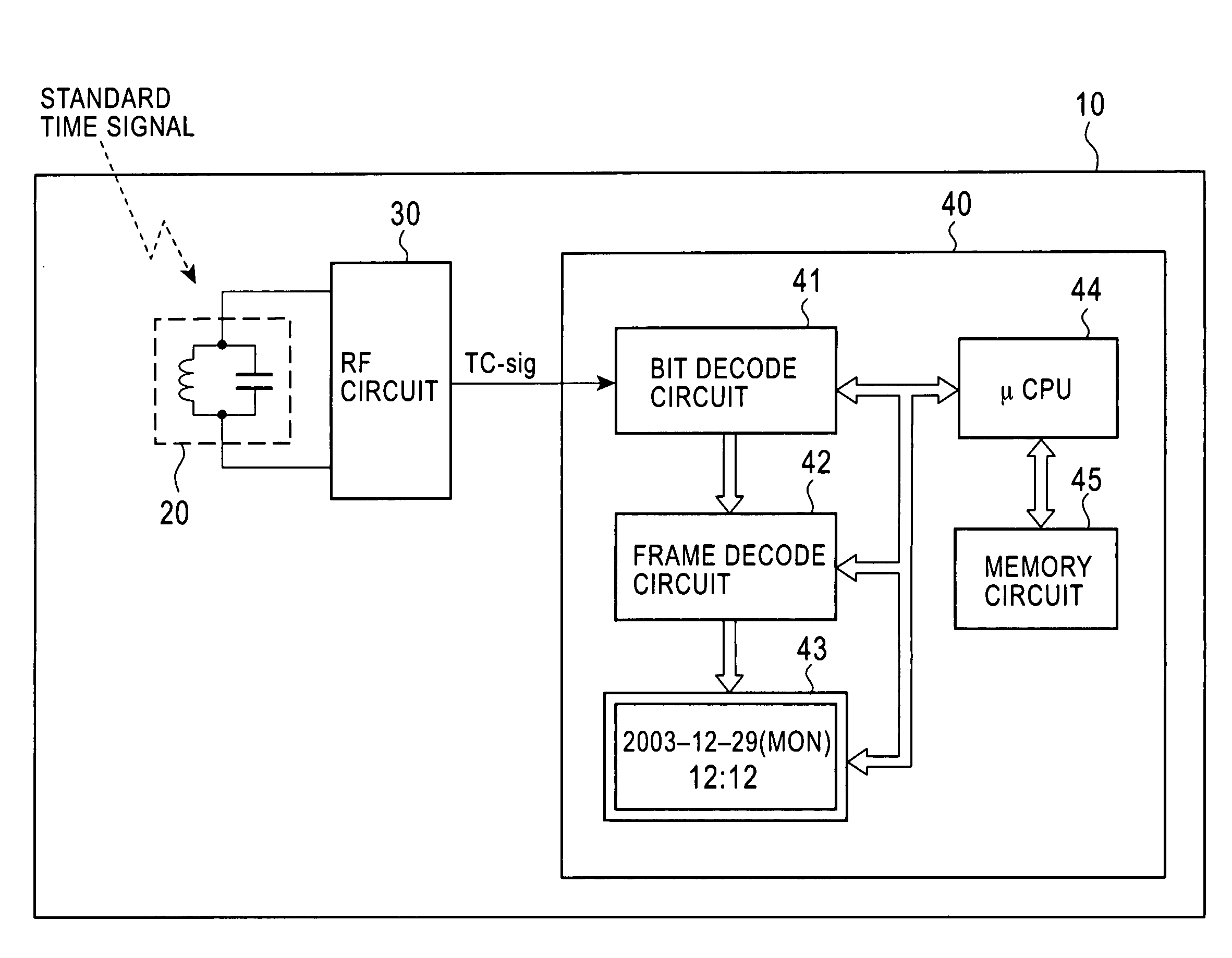
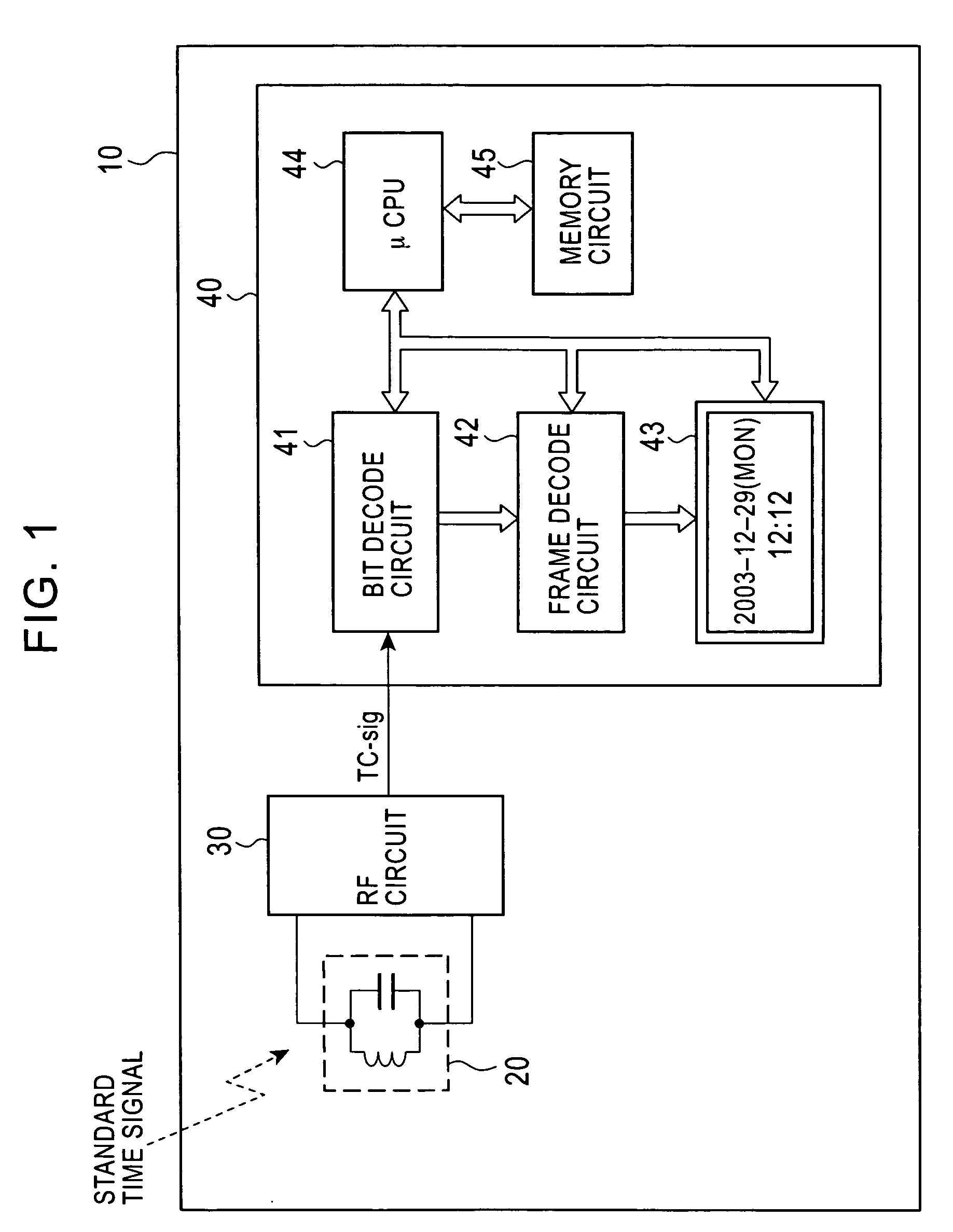
[0038] a radio controlled clock and a time code decoding method in the present invention will be explained on the basis of the block diagram shown in FIG. 1. An object of this embodiment is to realize exact bit synchronization of a code pulse included in a time code signal.

[0039] As shown in FIG. 1, the radio controlled clock 10 based on this embodiment is mainly constructed by an antenna 20, a radio frequency circuit 30 and a main processing circuit 40. Further, the main processing circuit 40 includes various circuits such as a bit decode circuit 41, a frame decode circuit 42, a display circuit 43, a microprocessor 44, a memory circuit 45, etc. In addition to this, for example, the radio controlled clock 10 includes various circuits such as a power circuit, an operation inputting circuit, etc. However, these circuits do not directly relate to the embodiment of the present invention. Therefore, their descriptions and explanations are omitted here.

[0040] Each constructional element ...

second embodiment

[0064] An object of this embodiment is to prevent a situation in which the normal decode of each code is prevented by the mixture of noises and the waveform distortion, and further improve the code judging ability explained in the

[0065] In the decoding method using the simple bit pattern judgment of the second embodiment, the code judgment was simply made by evaluating the matching score of the sampling data and the template pattern. However, in the real radio controlled clock, the time code signal supplied from the high frequency circuit 30 is transmitted via filtering processing, etc. using a low frequency pass filter within this circuit. Therefore, for example, there are many cases having a specific tendency in which jitter is caused in change timing from “L” to “H” or from “H” to “L” in the pulse waveform included in the time code signal, etc.

[0066] Therefore, if such a specific tendency caused in the time code signal is removed, the code judging result using the above matching...

third embodiment

[0082] In the third embodiment, a predetermined mask pattern is used to exclude a sampling point supposed to be large in the dispersion of the signal level from the object of the code judgment. Namely, the mask pattern becomes a pattern removing the point of large dispersion in the sampling data. In this embodiment, a standard deviation of the signal level at each sampling point is used as an evaluation reference value of the dispersion to evaluate the dispersion of data at such a sampling point.

[0083] This embodiment will be explained by using FIGS. 19A to 19E adopting a case in which the real TC signal corresponds to the binary 0 as sampling data as an example. Eight sampling data shown in FIG. 19A are the same as the sampling data shown in FIG. 6 of the second embodiment and FIG. 12 of the third embodiment.

[0084] In this embodiment, the standard deviation of the signal level at each sampling point from 0 to 19 with respect to the eight sampling data is first calculated. For exam...


PUM


Abstract

In a radio controlled clock and a decoding method of a time code signal, the time code signal can be accurately decoded irrespective of the mixture of noises and the deterioration of a radio wave signal receiving situation, and arithmetic processing is simple. A standard time signal is received and the time code signal superposed on this standard time signal is sampled at an interval of 50 ms and is stored to a memory. The stored sampling data are formed as a list in a data group every one second (20 samples). The plurality of data groups formed as a list are added every each sampling point, and a point for maximizing an increase change of the adding result is set to a synchronizing point of the sampling. Further, the correlation of the sampling data group and a code template pattern is calculated and a code shown by the sampling data group is judged.

Description

BACKGROUND OF THE INVENTION [0001] 1. Field of the Invention [0002] The present invention relates to a standard time signal receiving time device (hereinafter simply called a “radio controlled clock”) that performs time calibration by using a received a standard time signal and a decoding method of a time code signal superposed on the carrier wave of the standard time signal. [0003] 2. Description of the Related Art [0004] The time code signal indicating the Japanese standard time is continuously transmitted by a long radio wave from two domestic signal transmitting stations of the Kyushu long wave station and the Fukushima long wave station managed and controlled by the Communication General Institute of Japan as an independent corporation. Hereinafter, such a long radio wave is called a “standard time signal”. With respect to the standard time signal transmitted presently, two radio waves are used, of which the frequencies of the carrier waves are 40 kHz and 60 kHz respectively. E...

Claims


Application Information

Patent Timeline
Patent Type & Authority Applications(United States)
IPC IPC(8): G04G5/00G04R20/00G04R20/12H04L7/00
CPCG04R20/10G04G5/002
Inventor KONDO, TAKAYUKI
Owner LAPIS SEMICON CO LTD
Why Eureka
Try Eureka