Spatial reuse of frequency channels in a WLAN

a frequency channel and spatial reuse technology, applied in the field of wireless communications, can solve the problems of inability to decode ack messages and determine, and achieve the effect of enhancing the transmission capacity of the wlan and reducing latency and jitter

Inactive Publication Date: 2005-09-08
ALLIED TELESIS ISRAEL LTD
View PDF82 Cites 109 Cited by
  • Summary
  • Abstract
  • Description
  • Claims
  • Application Information

AI Technical Summary

Benefits of technology

[0015] In some embodiments of the present invention, two or more access points, in different parts of the WLAN, are each assigned to communicate with a respective group of stations. The access manager instructs each of the access points to communicate with the stations in its group in sequence, in such a way that one station in each group communicates with the access point to which it is assigned simultaneously with one of the stations in the other group. The access manager thus enforces a sort of time division multiplexing (TDM) among the stations in each group, which may be synchronized across two or more groups. This scheme is useful particularly in reducing latency and jitter in real-time applications, such as Voice over Internet Protocol (VoIP), that involve regular transmission of fixed-length data packets, but it may be used to enhance the capacity of the WLAN in transmission of all sorts of application traffic.

Problems solved by technology

Because the stations may transmit these uplink signals at higher power than the downlink transmissions of the access points, the access points may receive both uplink signals simultaneously and may therefore be unable to decode the ACK messages.
Furthermore, ACK packets (as defined in the 802.11 standard) do not identify the packet source.
Therefore, if the access points succeed in receiving only one ACK packet, it is not possible to determine from the content of the ACK packet which mobile station acknowledged the downlink signal and which did not.

Method used


Image

  • Spatial reuse of frequency channels in a WLAN
  • Spatial reuse of frequency channels in a WLAN
  • Spatial reuse of frequency channels in a WLAN

Examples


Embodiment Construction

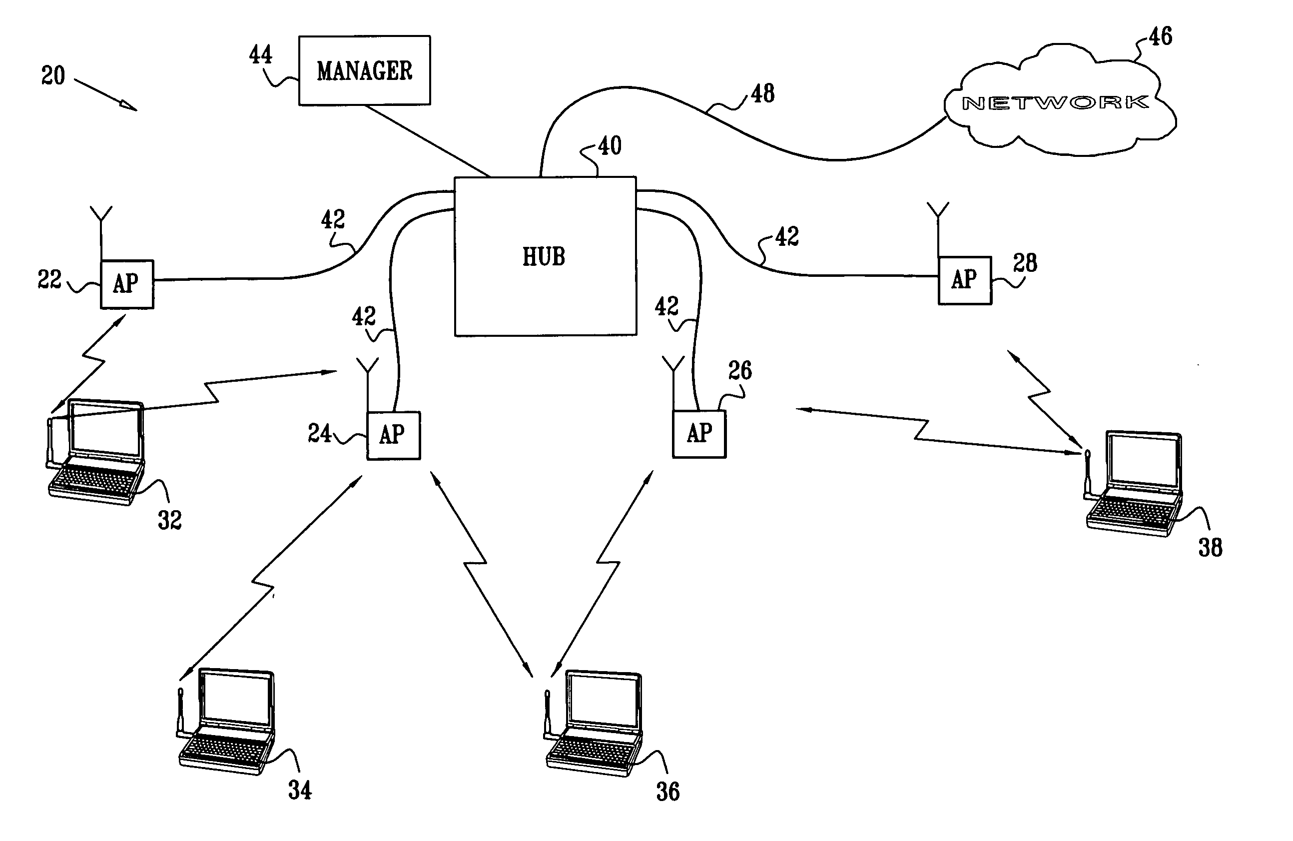
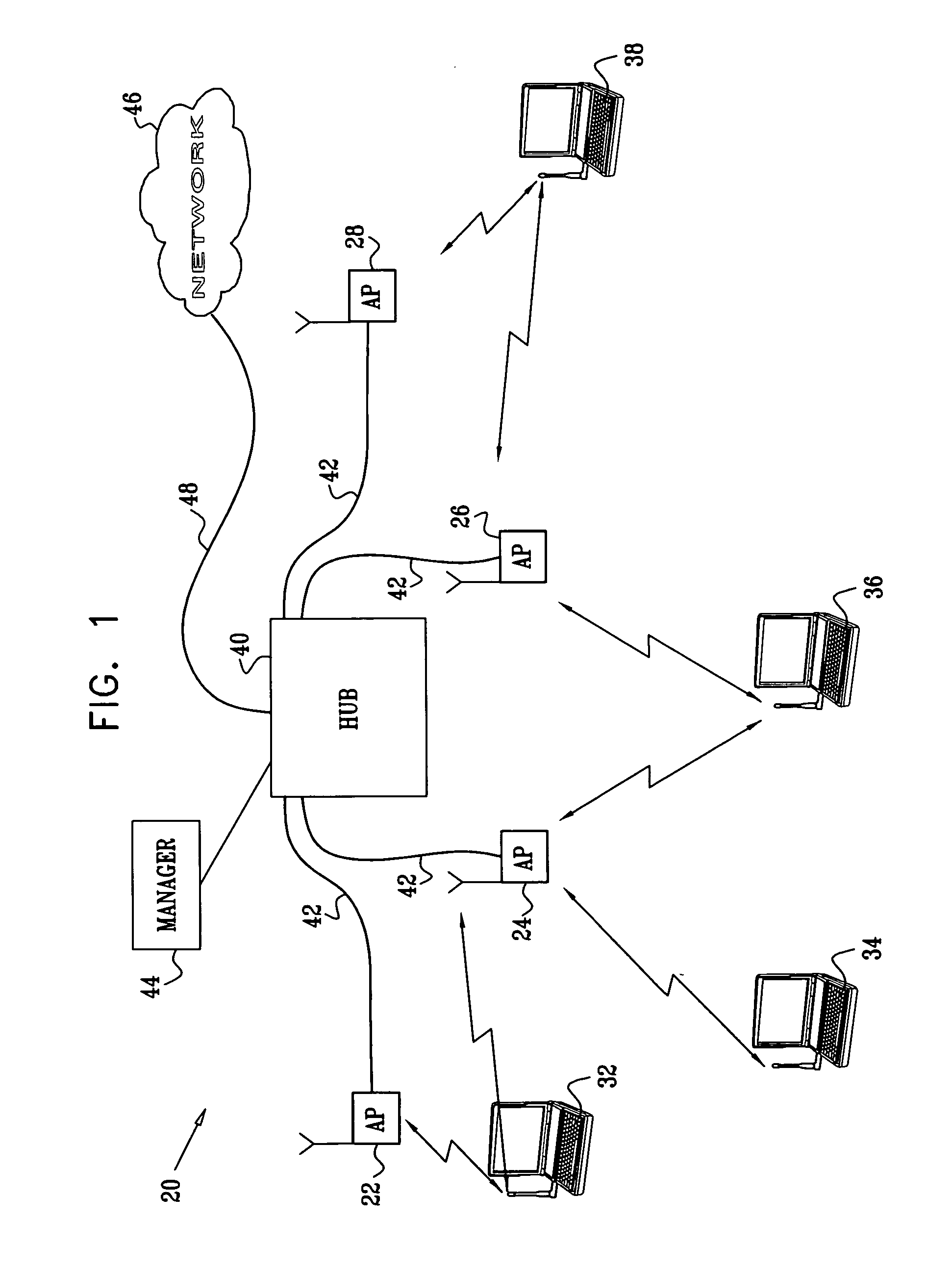
[0033]FIG. 1 is a block diagram that schematically illustrates a wireless LAN (WLAN) system 20, in accordance with a preferred embodiment of the present invention. System 20 comprises multiple access points 22, 24, 26, 28, which comprise PHY and MAC interfaces for data communication with mobile stations 32, 34, 36, 38. The mobile stations typically comprise computing devices, such as desktop, portable or handheld devices. In the exemplary embodiments described hereinbelow, it is assumed that the access points and mobile stations communicate with one another in accordance with one of the standards in the IEEE 802.11 family and observe the 802.11 MAC layer conventions described in the above-mentioned 802.11 standard. The principles of the present invention, however, may also be applied, mutatis mutandis, in other wireless environments, such as Bluetooth networks, personal area networks (IEEE 802.15), wireless metropolitan area networks (IEEE 802.16) and Ultra Wideband (UWB) networks. ...


PUM


Abstract

A method for communication includes arranging a first plurality of access points, including at least first and second access points, to communicate on a common frequency channel in a wireless local area network (WLAN) with a second plurality of mobile stations, comprising at least first and second mobile stations. The access points are linked to communicate with one another over a communication medium. A message is sent over the communication medium to at least one of the first and second access points so as to cause the first and second access points to simultaneously transmit downlink signals to the first and second mobile stations, respectively. The downlink signals are transmitted simultaneously from the first and second access points responsively to the message.

Description

CROSS-REFERENCE TO RELATED APPLICATIONS [0001] This application is a continuation-in-part of U.S. patent application Ser. No. 10 / 285,869, filed Nov. 1, 2002, which is a continuation-in-part of U.S. patent application Ser. No. 10 / 214,271. This application is also a continuation-in-part of a U.S. patent application entitled “Spatial Reuse of Frequency Channels in a WLAN,” filed Mar. 3, 2005. These related applications are assigned to the assignee of the present patent application, and their disclosures are incorporated herein by reference.FIELD OF THE INVENTION [0002] The present invention relates generally to wireless communications, and specifically to methods and devices for improving the performance of wireless local area networks. BACKGROUND OF THE INVENTION [0003] Wireless local area networks (WLANs) are gaining in popularity, and new wireless applications are being developed. The original WLAN standards, such as “Bluetooth” and IEEE 802.11, were designed to enable communication...

Claims


Application Information

Patent Timeline
Patent Type & Authority Applications(United States)
IPC IPC(8): H04B1/69H04B7/005H04L12/28H04L12/56H04W52/08H04W52/40H04W84/12H04W88/08
CPCH04B1/7163H04W4/06H04W92/20H04W52/40H04W84/12H04W52/08
Inventor SHPAK, ERAN
Owner ALLIED TELESIS ISRAEL LTD
Why Eureka
Try Eureka