Method and apparatus for segmenting a microarray image

a microarray and image technology, applied in the field of microarrays, can solve the problems of small variations, scan mechanism location accuracy errors in the scanner, and the nominal grid rarely aligns well with the underlying scanned microarray image, and achieves image segmentation, reduces or eliminates the amount of time required, and is accomplished very quickly and simply.

Inactive Publication Date: 2005-09-08
PERKINELMER HEALTH SCIENCES INC
View PDF12 Cites 3 Cited by
  • Summary
  • Abstract
  • Description
  • Claims
  • Application Information

AI Technical Summary

Benefits of technology

[0026] Since microarrays produced under the same conditions have very similar geometric errors, using a pre-modified nominal grid produced as aforesaid reduces or eliminates the amount of time required for subsequent image segmentation according to the present method. Indeed in many cases, no further alignment of the grid is needed, especially if the grid markers are smaller than the microarray spots. If the markers are larger than random spot location erro...

Problems solved by technology

In practice, a nominal grid rarely aligns well with the underlying scanned microarray image due to the combined effects of various tolerances in the spotting instrument.
These include variations in the locations of the pin tips in the spotter's print head, misalignment of the print head with the spotter's x/y motion axes, non-orthogonality of the spotter's motion axes, spotter robot motion accuracy errors, and microarray substrate location errors in the spotter.
There also may be scanning mechanism location accuracy errors in the scanner which scans the microarray image during the segmentation process.
Some of these errors are systematic in that they are repeatable for every microarray printed by a particular spotter, some errors are repeatable within a batch of printed arrays and some errors are random.
A random spot location error may be caused by random variations in the motion of the print head in a given spotter which may cause small variations in the locations of individual spots within each block of the microarray.
However, if the blocks in the microarray image are not rectangular, but have other shapes such as a parallelogram or a trapezoid, such errors cannot be addressed by simply translating, rotating or scaling the nominal grid.
In other words, the prior segmentation programs do not allow for changing the overall shape of ...

Method used


Image

  • Method and apparatus for segmenting a microarray image
  • Method and apparatus for segmenting a microarray image
  • Method and apparatus for segmenting a microarray image

Examples


Embodiment Construction

[0035] The present invention may be implemented as program instructions for configuring a microarray image analysis or quantitation workstation such as the one shown at 10 in FIG. 7. As shown there, workstation 10 may include a central processing unit (CPU) 12 which operates on program instructions in a memory 14 using a processor in CPU 12. A scanner 16 scans microarrays to obtain corresponding image data which may be stored in an image storage device 18 connected to CPU 12. A user may input instructions concerning the microarray image analysis by way of a keyboard 20 or a mouse 22 connected to CPU 12 and images and other data may be displayed on a monitor 23. Also, the workstation usually includes a printer 24 for printing images and data. Image data representing the nominal grid may be loaded into the workstation via a disk drive 26 and stored in memory 14 along with the program instructions for implementing the present invention.

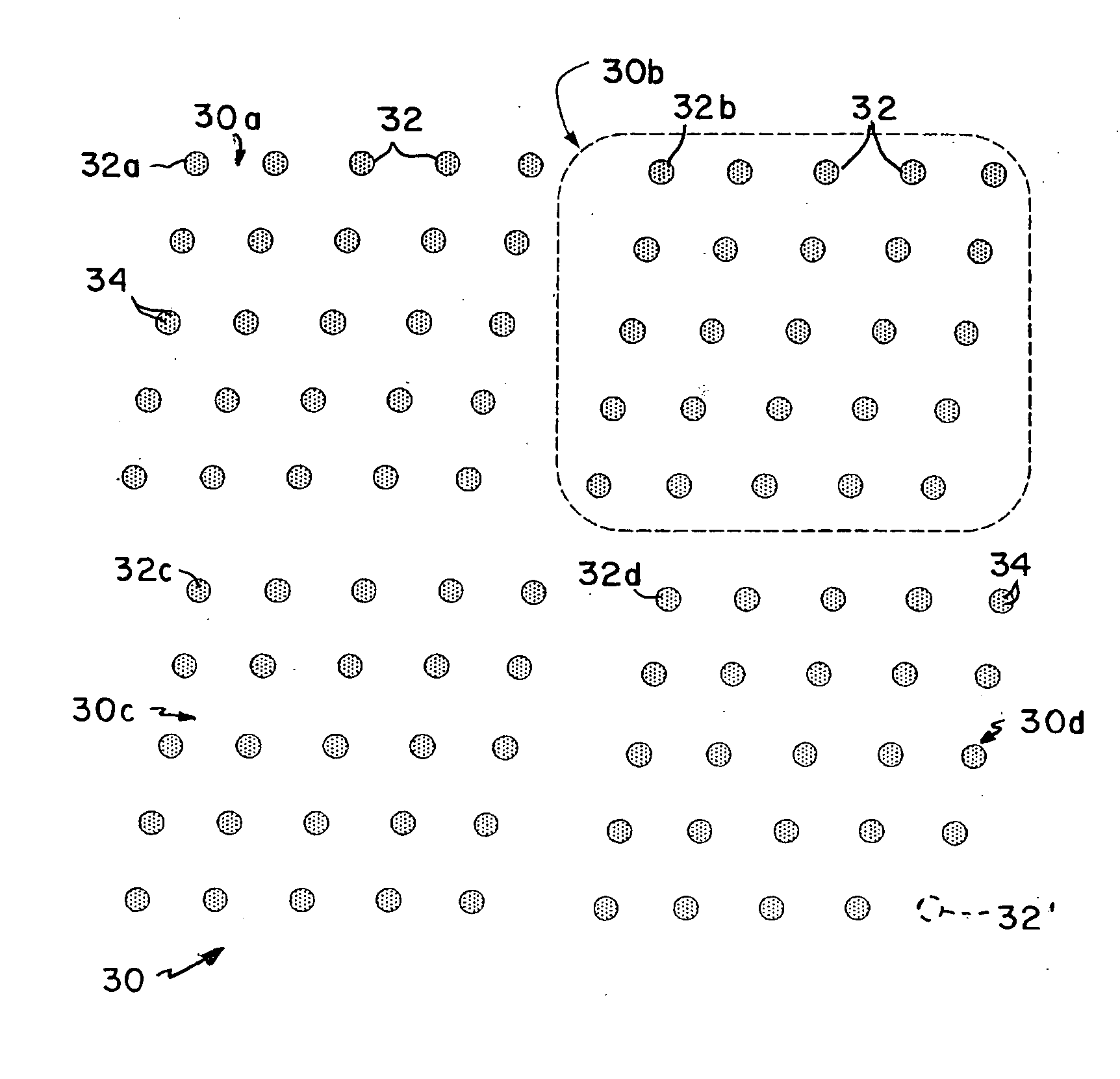
[0036] Refer now to FIG. 1 which illustrates an e...


PUM


Abstract

In a method for providing rapid and simple manually driven alignment of image segmentation grids to images of imperfect mircroarrays, an image of a microarray composed of multiple sub-arrays or blocks is displayed and a nominal grid composed of corresponding sub-arrays or blocks is superimposed on that image. Comer markers of a grid block are dragged to coincide with the spots at the corresponding corners of the underlying image block. The locations of the intervening grid markers in that block are automatically adjusted by linear interpolation in two dimensions. The corrections generated for this grid block are then applied automatically to all of the other blocks in the grid. Following this, the corner grid blocks are dragged to align a single corner marker within each corner grid block with an image spot at the corresponding corner block of the image, and all of the intervening grid blocks are automatically aligned to these by linear interpolation in two dimensions.

Description

CROSS-REFERENCE TO RELATED APPLICATION [0001] The present application claims the benefit of U.S. Provisional Application Ser. No. 60 / 521184, filed on Mar. 5, 2005, which is hereby incorporated by reference herein.BACKGROUND OF THE INVENTION [0002] This invention relates to microarrays. It relates more particularly to a method and apparatus for locating spots in a microarray image, also referred to as image segmentation. [0003] A microarray is an array of very small samples of chemical or biochemical material drawn from reservoirs by a spotting instrument or spotter and deposited as a grid of many such spots on a solid substrate such as a glass microscope slide. When the microarray is exposed to selected probe material including a label molecule such as a fluorophore, the probe material selectively binds to the target sites only where complimentary binding spots are present through a process called hybridization thereby providing an assay. The microarray may then be scanned by a flor...

Claims


Application Information

Patent Timeline
IPC IPC(8): G21K1/00G06V10/24
CPCG06K9/32G06V10/24
Inventor GEHRIG, JAY S.JAVALI, HEMANTHA D.
Owner PERKINELMER HEALTH SCIENCES INC
Why Eureka
Try Eureka