Image forming apparatus
- Summary
- Abstract
- Description
- Claims
- Application Information
AI Technical Summary
Benefits of technology
Problems solved by technology
Method used
Image

Examples
first embodiment
(Overall Structure and Operation of Image Forming Apparatus)
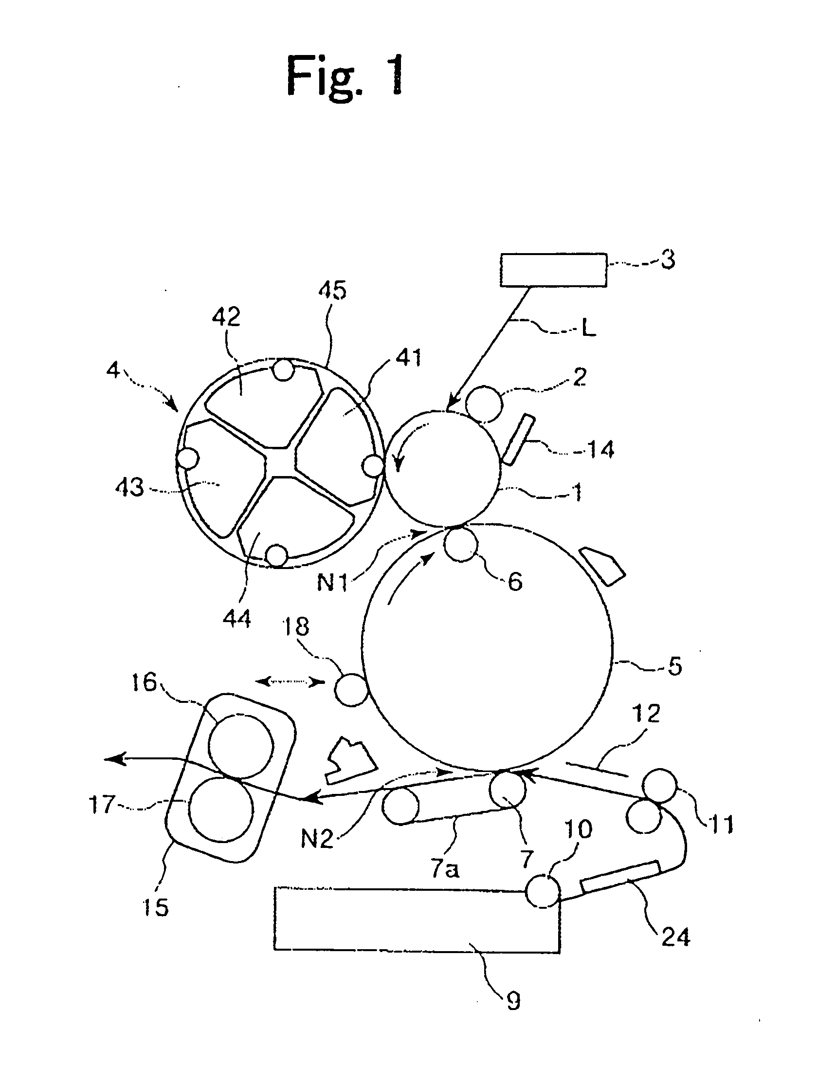
[0031] First, description is made of overall structure and operation of an image forming apparatus according to this embodiment of the present invention. FIG. 1 schematically shows an overall structure of an image forming apparatus 100 of this embodiment. In this embodiment, the image forming apparatus 100 is a color-image forming apparatus of an intermediate transfer system employing an electrophotographic process, such as a copying machine or a laser beam printer.
[0032] The image forming apparatus 100 includes as a first image bearing member a rotary drum type electrophotographic photosensitive member (hereinafter, referred to as “photosensitive drum”) that is repeatedly used. A photosensitive drum 1 is rotated at a predetermined peripheral speed (process speed) in a counterclockwise direction as indicated by the arrow of FIG. 1.
[0033] The photosensitive drum 1 is uniformly charged to a predetermined potential with a ...
second embodiment
[0080] Next, another embodiment of the present invention is described. Basic structure and operation of the image forming apparatus of this embodiment are the same as the image forming apparatus 100 of the first embodiment. Hereinafter, description is made focusing the feature of this embodiment.
[0081] This embodiment has a feature that the toner slippage through the cleaning blade 14 is avoided as mentioned in the first embodiment, and in addition, the noise generated by the unstable behavior of the cleaning blade 14 is prevented.
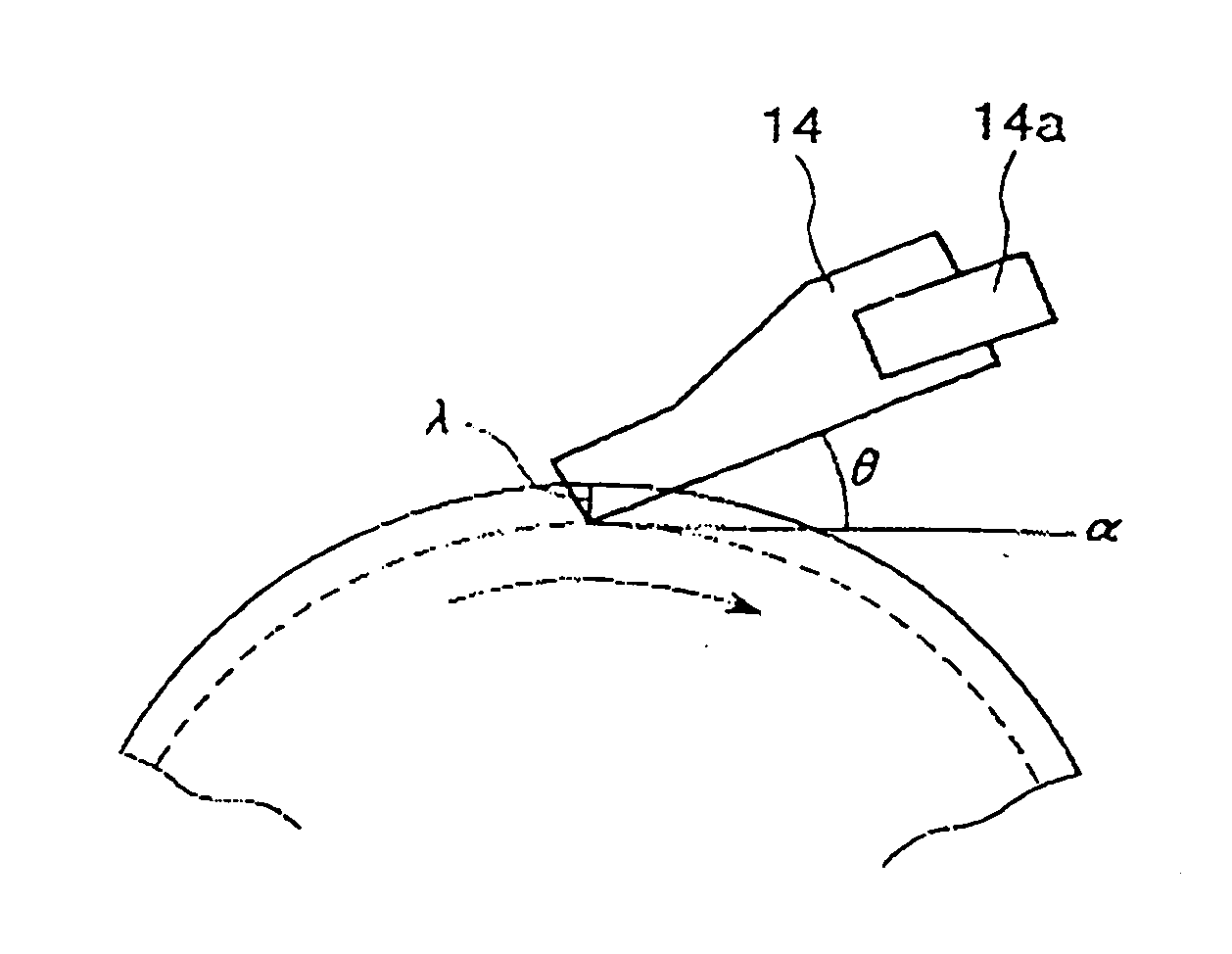
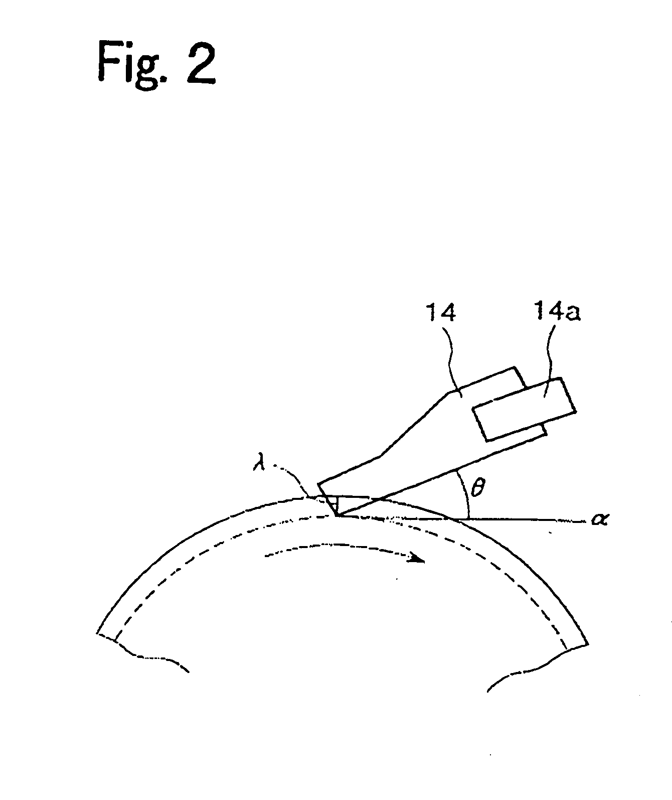
[0082] That is, this embodiment has a feature that in the image forming apparatus shown in FIG. 1, the degree of compaction C of the toner is set to fall within the range described in the first embodiment, and at the same time, the set angle 0 of the cleaning blade 14 to the photosensitive drum 1 is set to 27° or smaller.
[0083] In general, if the set angle of the blade increases, the same inroad amount of the blade leads to the enhanced cleaning perform...
third embodiment
[0088] Next, another embodiment of the present invention is described.
Overall Structure and Operation of Image Forming Apparatus)
[0089]FIG. 4 is a schematic diagram showing an image forming apparatus 200 according to this embodiment. In FIG. 4, the same or equivalent components as or to the image forming apparatuses according to the first and second embodiments are denoted by the same reference numerals. Basic structure and operation of the image forming apparatus 200 of this embodiment are almost the same as those of the first and second embodiments.
[0090] In this embodiment, the belt-type intermediate transfer belt 5 as the intermediate transfer member is provided as the second image bearing member. In this embodiment, the single-color developing device 4 is used as the developing means. The toner image formed on the photosensitive drum 1 is immediately transferred onto the intermediate transfer belt 5 at the primary transfer nip portion N1 and then transferred onto the transf...
PUM
 Abstract
Description
Claims
Application Information
 - R&D
- Intellectual Property
- Life Sciences
- Materials
- Tech Scout
- Unparalleled Data Quality
- Higher Quality Content
- 60% Fewer Hallucinations
Browse by: Latest US Patents, China's latest patents, Technical Efficacy Thesaurus, Application Domain, Technology Topic, Popular Technical Reports.
© 2025 PatSnap. All rights reserved.Legal|Privacy policy|Modern Slavery Act Transparency Statement|Sitemap|About US| Contact US: help@patsnap.com