
Eureka
For R&D, Eureka makes reading and utilizing patents & technical documents easy.
Eureka AIR
Designed for self-driven R&D workflows. Generate viable solutions, solve complex R&D challenges, empower your innovation with AI.

Eureka Materials
Designed for material experts only. Revolutionize your material R&D, from search, analyze, to developing new materials.

TechResearch
Generate reliable direction feasibility study reports for your R&D in just a few steps.

TechSeek
Discover and master advanced knowledge NOW. Basics, ideas, possibilities, all at once.

TechMind
As an expert in R&D Theories, TechMind can generates customized viable solutions instantly.

TechRisk
Analyze your overall solution with one click, know your potential R&D risks in advance.

TechMonitor
Get weekly tech updates, stay abreast of the latest tech innovations and key insights.
Machine tool provided with cooling mechanism
- Summary
- Abstract
- Description
- Claims
- Application Information
AI Technical Summary
Benefits of technology
Problems solved by technology
Method used
Image

Examples
first embodiment
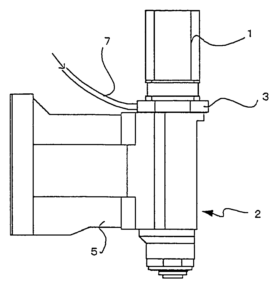
[0021] a machine tool provided with a cooling mechanism according to the present invention will now be described with reference to FIGS. 1 and 2.
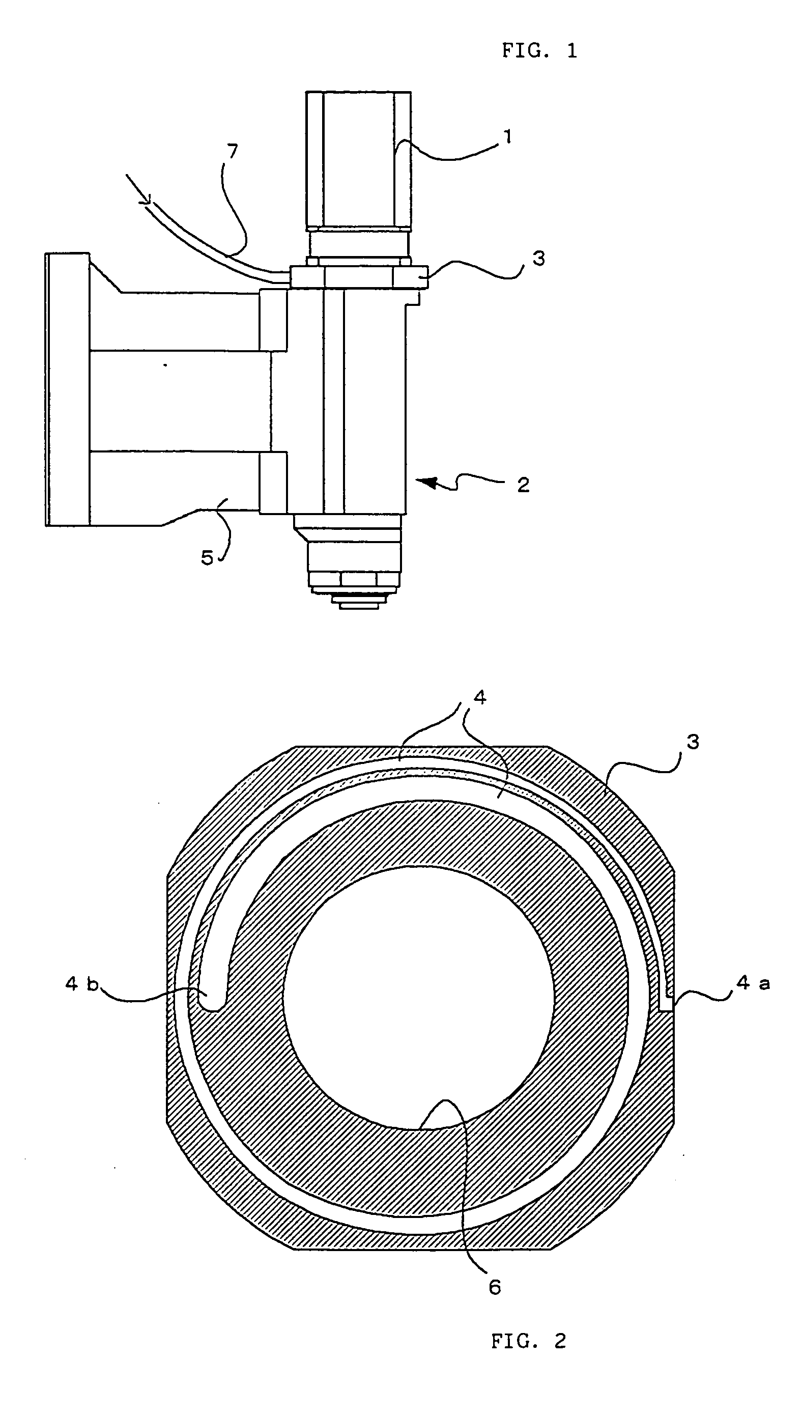
[0022] The machine tool of the present embodiment is a machining center using as its spindle motor 1 a motor that is located as a part independent of a spindle. As shown in FIG. 1, a headstock 5 of a spindle head 2 moves in the vertical direction of FIG. 1, guided by a column (not shown). The spindle motor 1 is mounted on the spindle head 2 through a cooling flange 3. The spindle (not shown) in the spindle head 2 is driven as the spindle motor 1 is operated.
[0023]FIG. 2 is a view showing a cross section of the cooling flange 3 in a direction perpendicular to the shaft axis of the spindle motor 1. The flange 3 is about 20 to 30 mm thick and has therein a cooling passage 4 through which passes air or some other gas for use as a refrigerant. The cooling passage 4 is a convolute passage having a gas inlet 4a at one end and a gas outlet 4b at t...
second embodiment
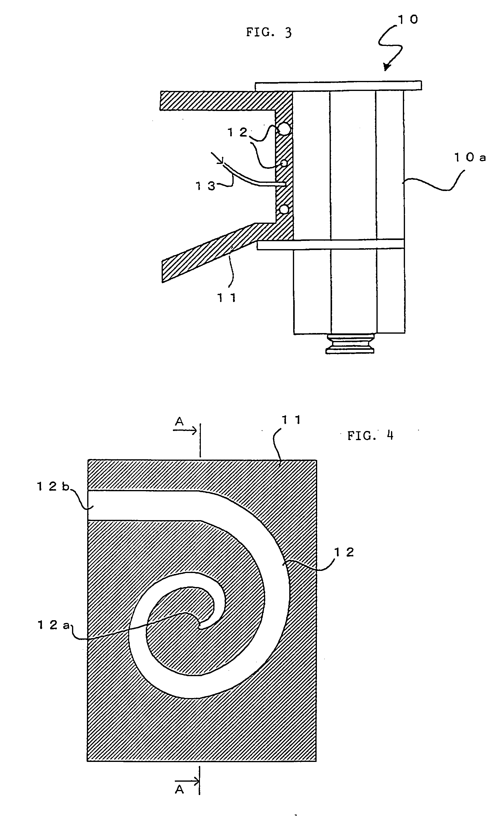
[0026] the machine tool provided with the cooling mechanism according to the present invention will now be described with reference to FIGS. 3 and 4.
[0027] The machine tool of the present embodiment is a machine of a built-in motor type. In the built-in-motor type machine tool, heat generated from a spindle motor and a bearing is transmitted to a shaft, spindle head, column, etc., thereby expanding thermally them. Since the shaft extends mainly in its length direction only, it cannot easily tilt the machine. If the heat is transferred to the spindle head or column, however, the machine body may be tilted.
[0028] In the present embodiment, therefore, a spindle head 10 is composed integrally of a spindle motor 10a and a spindle (not shown), and a cooling passage 12 is provided in that part of a headstock 11 of the spindle head 10 which is situated closer to the spindle motor 10a, as shown in FIG. 3.
[0029]FIG. 4 is a sectional view of the part of the headstock 11 of FIG. 3 near the sp...
PUM
| Property | Measurement | Unit |
|---|---|---|
| Pressure | aaaaa | aaaaa |
| Distance | aaaaa | aaaaa |
Abstract
Description
Claims
Application Information
 - R&D Engineer
- R&D Manager
- IP Professional
- Industry Leading Data Capabilities
- Powerful AI technology
- Patent DNA Extraction
Browse by: Latest US Patents, China's latest patents, Technical Efficacy Thesaurus, Application Domain, Technology Topic, Popular Technical Reports.
© 2024 PatSnap. All rights reserved.Legal|Privacy policy|Modern Slavery Act Transparency Statement|Sitemap|About US| Contact US: help@patsnap.com