
Method for heating a battery in a hybrid electric vehicle

Inactive Publication Date: 2005-09-08
FORD GLOBAL TECH LLC
View PDF7 Cites 21 Cited by
  • Summary
  • Abstract
  • Description
  • Claims
  • Application Information

AI Technical Summary

Benefits of technology

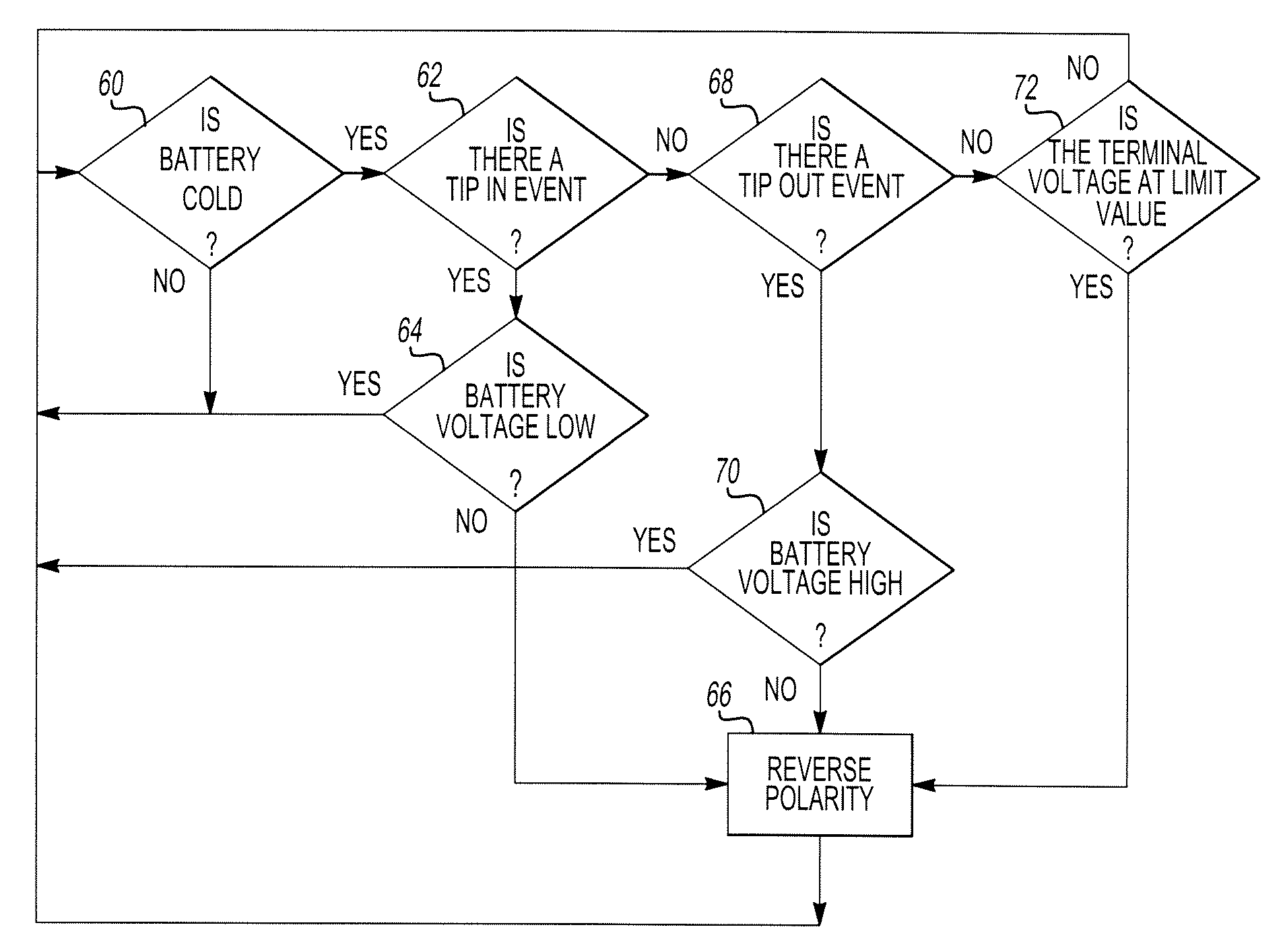
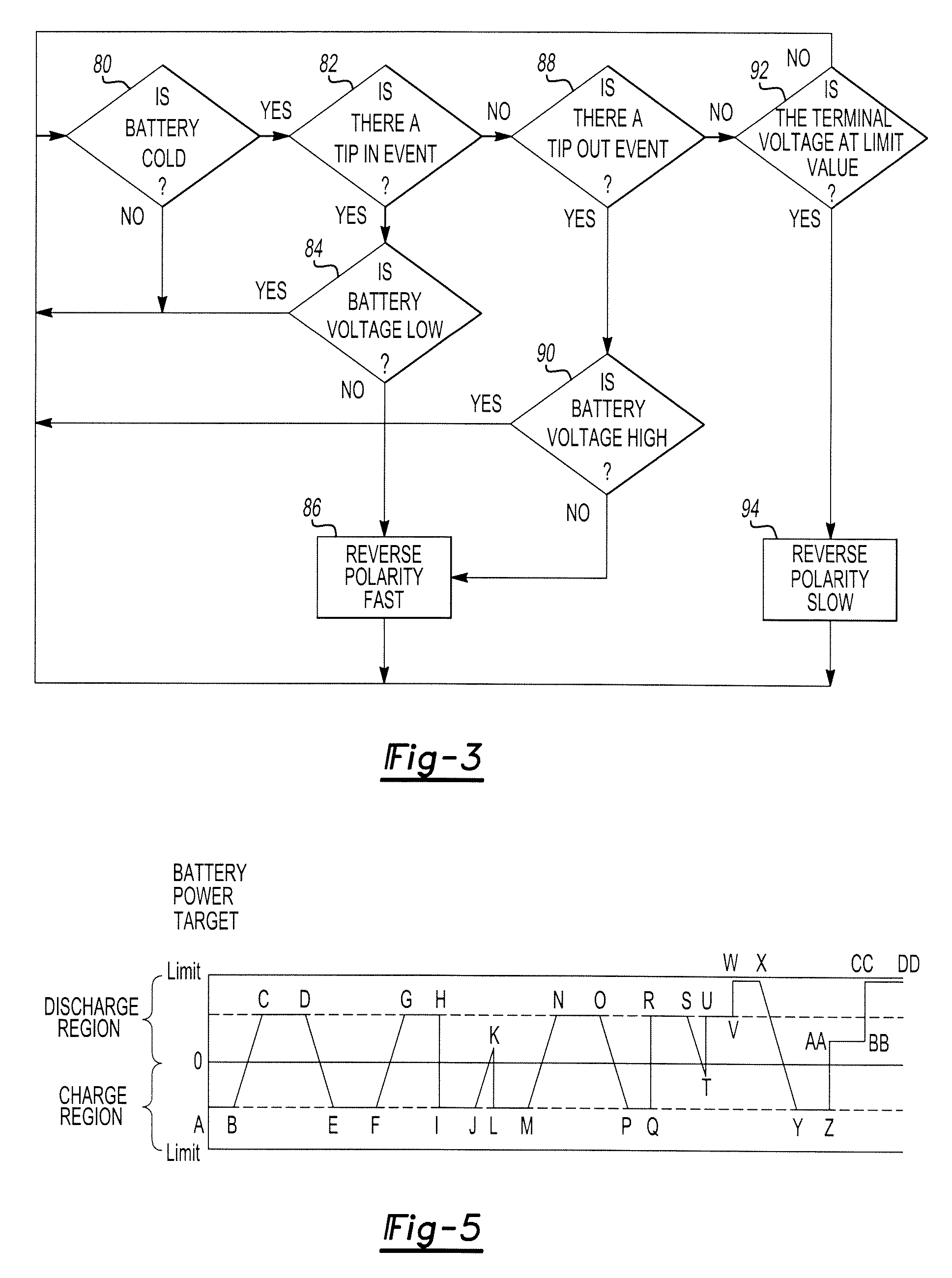
[0012] The step of determining whether a previous polarity reversal has been completed may include determining whether the battery is charging or discharging after determining whether the previous polarity reversal has been completed. The step of reversing the polarity of the battery current may include calculating a power target level and reversing the polarity of the battery to the power target level. The step of determining whether a terminal voltage event has occurred may include determining whether the terminal voltage value is greater than a first limit value if the battery is discharging and determining whether the terminal voltage value is less than a second limit value if the battery is charging.
[0013] According to

Problems solved by technology

In general, the battery performs poorly at cold temperatures.
As a result, the peak charge of the battery is limited and the peak battery discharge capability is reduced.
Poor battery performance reduces torque to the vehicle wheels when battery power is utilized to propel the vehicle and increases reliance on the internal combustion engine.
Greater reliance on the engine increases vehicle emissions and decreases fuel economy.
In addition, poor cold temperature battery performance could result in the need to add external or secondary battery heating devices to the hybrid electric vehicle.
However, battery current polarity reversals may be noticeable to vehicle occupants.
For example, polarity reversals may be manifested as noise, intermittent engine revving, and hesitation in vehicle acceleration and may be particularly noticeable when cruising at a steady speed.

Method used


Image

  • Method for heating a battery in a hybrid electric vehicle
  • Method for heating a battery in a hybrid electric vehicle
  • Method for heating a battery in a hybrid electric vehicle

Examples


Embodiment Construction

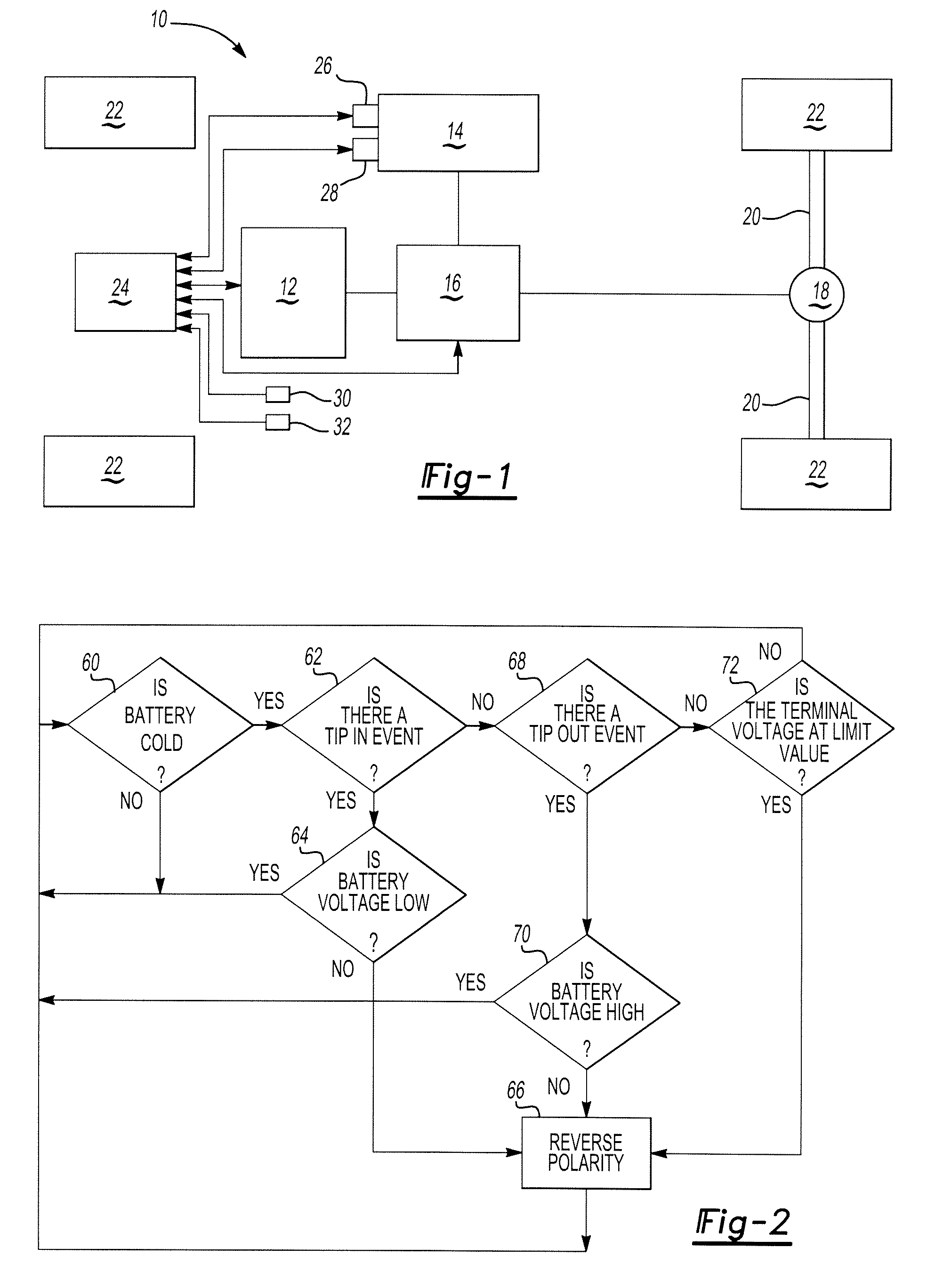
[0019] Referring to FIG. 1, a schematic of a hybrid electric vehicle 10 is shown. The hybrid electric vehicle 10 may have various drive train configurations, including a series hybrid drive, parallel hybrid drive, or split hybrid drive as is known by those skilled in the art. In addition, the hybrid electric vehicle 10 may be configured with energy recovery devices, such as a regenerative braking system.

[0020] The hybrid electric vehicle 10 includes an engine 12 and a battery 14 as power sources. The battery 14 may be a single cell battery or a battery pack comprising multiple bat or cells that are electrically interconnected. Power from the engine 12 or the battery 14 is provided to a motor-generator 16. The motor-generator 16 is adapted to the drive vehicle traction wheels. Specifically, the motor-generator 16 is connected to a differential 18 that is connected to a pair of axles 20 that are each connected to a vehicle wheel 22.

[0021] A control module 24 is used to monitor and c...


PUM


Abstract

A method for heating a battery in a hybrid electric vehicle. The hybrid electric vehicle has an engine, a battery, a motor generator powered by the engine or the battery, and a control module. The method includes the steps of determining a battery temperature and determining whether a tip-in event, a tip-out event, or a terminal voltage event has occurred. The polarity of the battery is reversed if the battery temperature is below a predetermined value and if a tip-in event, a tip-out event, or a terminal voltage event has occurred.

Description

BACKGROUND OF INVENTION [0001] 1. Field of the Invention [0002] The present invention relates generally to the operation of hybrid vehicles, and more particularly to the operation of a battery system of a hybrid electric vehicle. [0003] 2. Background Art [0004] Hybrid electric vehicles use an internal combustion engine and a battery as power sources for vehicle propulsion. In general, the battery performs poorly at cold temperatures. Specifically, cold temperatures affect battery chemistry and increase electrical resistance within the battery. As a result, the peak charge of the battery is limited and the peak battery discharge capability is reduced. Poor battery performance reduces torque to the vehicle wheels when battery power is utilized to propel the vehicle and increases reliance on the internal combustion engine. Greater reliance on the engine increases vehicle emissions and decreases fuel economy. In addition, poor cold temperature battery performance could result in the nee...

Claims


Application Information

Patent Timeline
IPC IPC(8): B60W20/00B60K6/48B60L3/00B60L50/16B60W10/26H01M10/44H01M10/50
CPCB60K6/48Y02T10/70B60L11/14B60L11/1861B60L11/187B60L11/1875B60W10/26B60W2510/246Y02T10/6221Y02T10/7005Y02T10/7044Y02T10/705Y02T10/7077Y10S903/907B60L3/0046B60W2510/244B60L50/16B60L58/12B60L58/24B60L58/27Y02T10/62Y02T10/7072B60K6/20B60K6/28
Inventor PREMA, MUKUNDA V.KOZAREKAR, SHAILESH S.OCHOCINSKI, CHRISTOPHER A.TAENAKA, ROBERT K.FREYERMUTH, VINCENTZHU, DOUGLAS
Owner FORD GLOBAL TECH LLC
Learn More