
Network architecture for data transmission

a network architecture and data technology, applied in the field of network architecture for data transmission, to achieve the effect of reducing bandwidth requirements

Active Publication Date: 2005-09-08
BLOOMBER FINANCE LP
View PDF14 Cites 79 Cited by
  • Summary
  • Abstract
  • Description
  • Claims
  • Application Information

AI Technical Summary

Benefits of technology

[0006] Generally speaking, the invention provides for providing requested content, such as multimedia content, in a format suitable for transmission over existing unicast communication links and then subsequently changing the content to a multicast format for local distribution. This allows an application provider to transmit a single unicast stream of content to, e.g., a client-side media server in a local area network (LAN), and then distribute it to multiple interested users within the LAN using a multicasting transmission format. This significantly reduces bandwidth requirements by providing a single unicast transmission to a LAN rather than supplying each user within the LAN with a dedicated content stream.

Problems solved by technology

Multicasting, unicast, and broadcast transmission all involve bandwidth issues that are of particular concern to network service providers.

Method used


Image

  • Network architecture for data transmission
  • Network architecture for data transmission
  • Network architecture for data transmission

Examples


Embodiment Construction

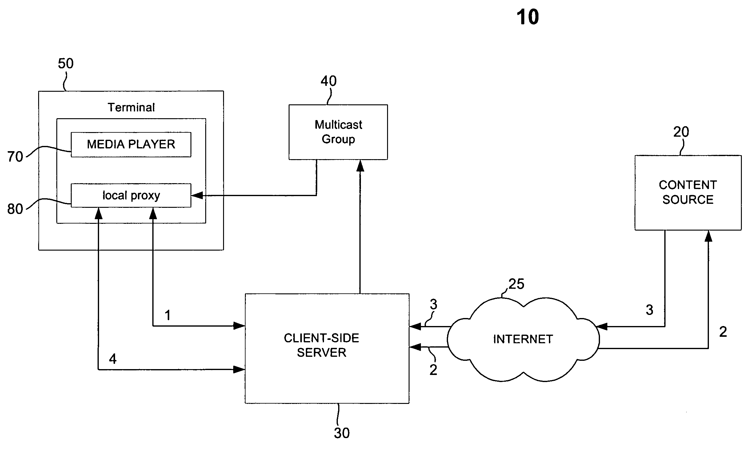
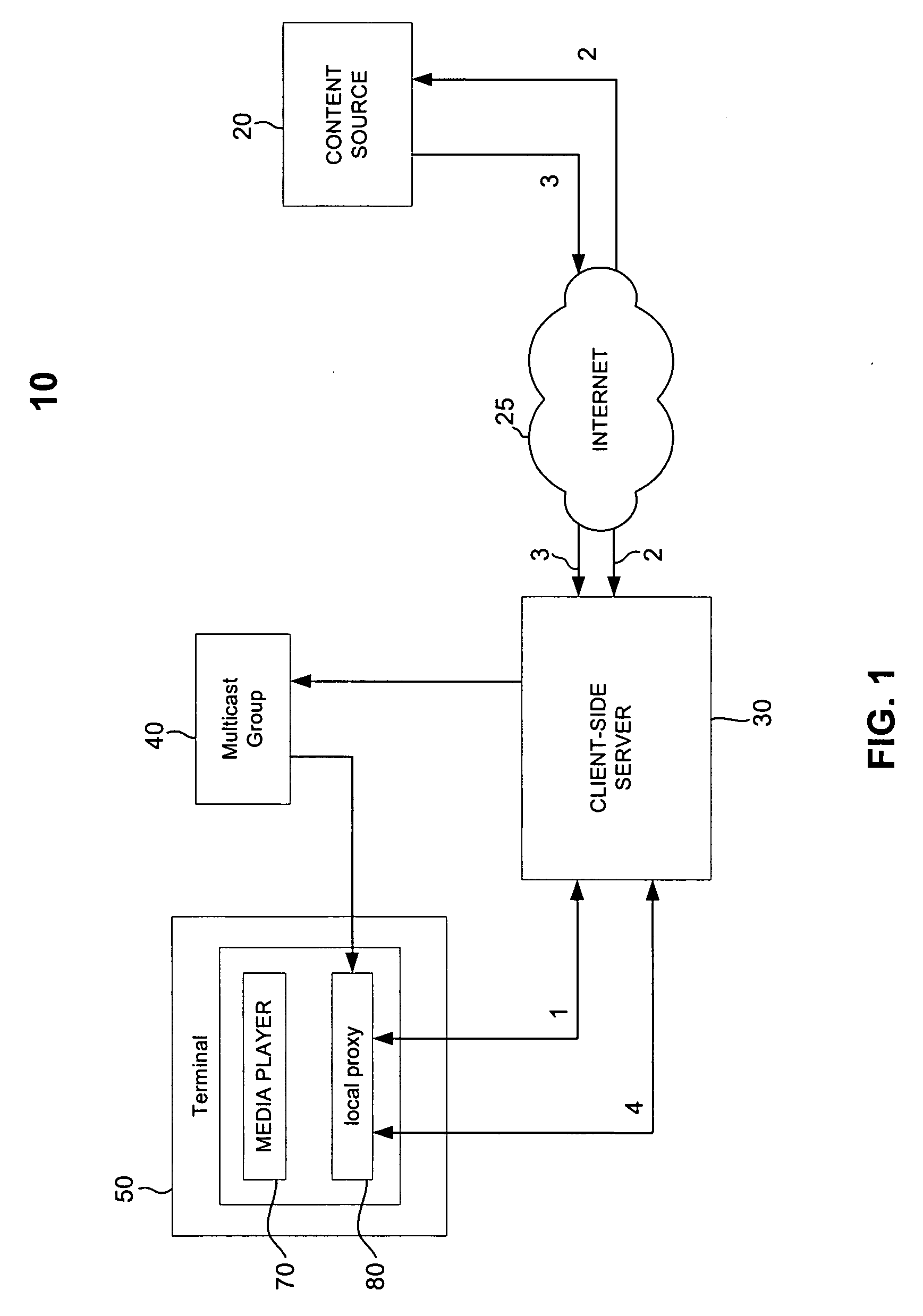
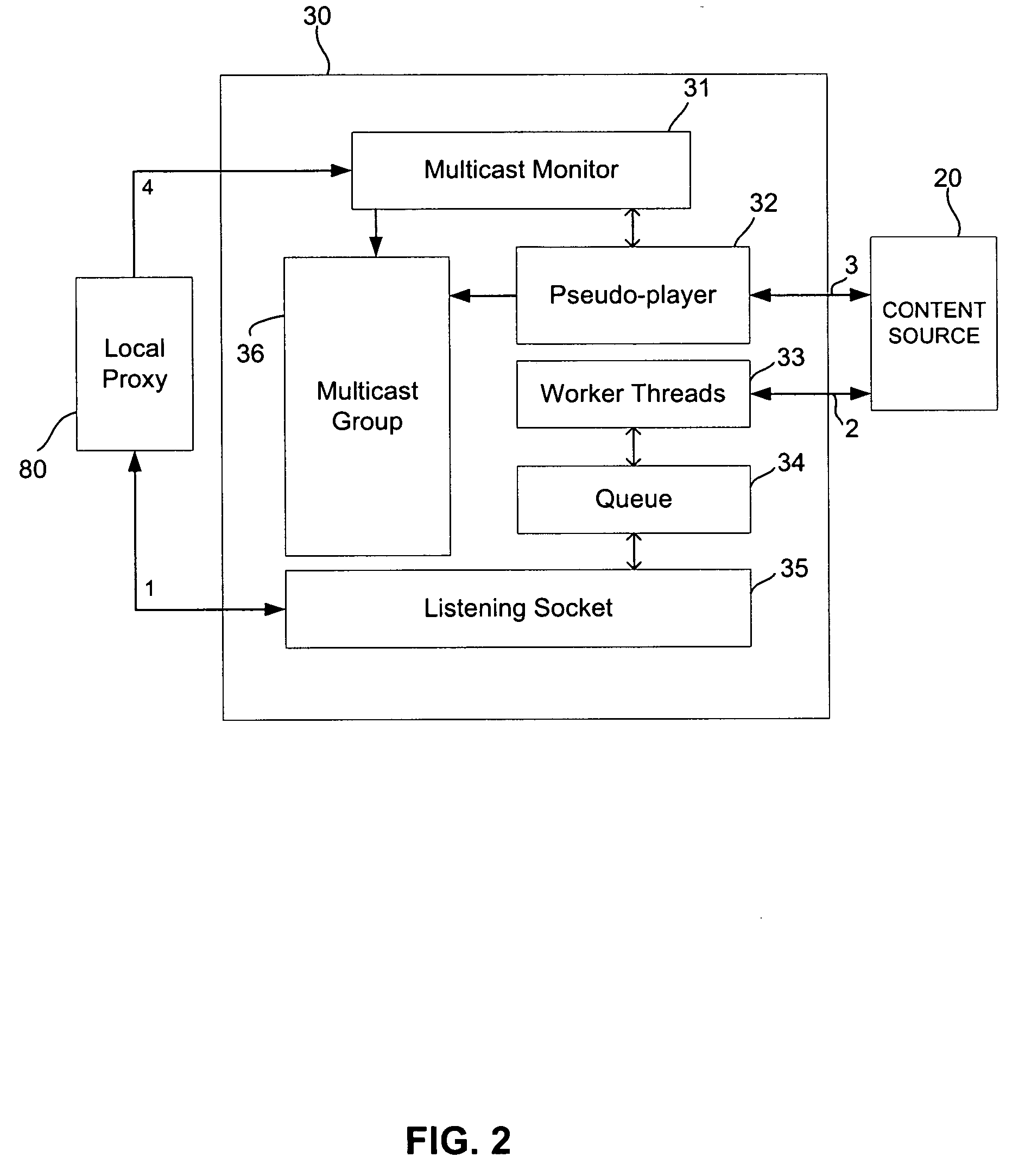
[0018]FIG. 1 is a block diagram of a content distribution network 10 constructed in accordance with the principles of the present invention. As shown, network 10 includes an electronic content source 20 coupled to a client-side server 30 through Internet 25. Although depicted as a server in FIG. 1, content source 20 may be any type of remote computer, network, database or other repository suitable for storing and retrieving electronic content. Similarly, client-side server 30 may be any suitable computer, network, or other electronic processing unit capable of requesting, receiving, and / or manipulating content streams as further described herein. In some embodiments, content source 20 and client-side server 30 may be configured similarly or identically to one another (e.g., server 30 may be configured as a “headless terminal” version of source 20). Client-side server 30 may include proprietary or other specialized software and / or hardware for manipulating or modifying content stream...


PUM


Abstract

A content distribution network with client side multicasting properties that operates with a reduced bandwidth is provided. The arequested content, such as multimedia content, is provided in a format suitable for transmission over existing unicast communication links and is then changed to a multicast format for local distribution. This allows an application provider to transmit a single unicast stream of content to a client-side media server in a local area network (LAN) and then distribute it to multiple interested users within the LAN using a multicasting transmission format. This significantly reduces bandwidth requirements by providing a single unicast transmission to a LAN rather than supply each user within the LAN with a dedicated content stream.

Description

[0001] The invention relates to improvements in data transmission networks, and, more particularly, to network arrangements that reduce the amount of bandwidth required to transmit information to multiple network users. BACKGROUND OF THE INVENTION [0002] Many different types of information may be transmitted from one point on a computer network to another. Such information is sometimes referred to as “content” which may include various forms or combinations of electronic information such as text, audio, and / or visual information (often referred to as multimedia content). One form of content transmission across a network is through a technique known as “streaming.” Using this streaming technique, a person at a remote computer terminal may request content over the Internet or other network which is subsequently “streamed” to the content requester. Employing one of several widely available media players such as Windows Media Player™, or RealOne Player™, the user may quickly and easily ...

Claims


Application Information

Patent Timeline
Patent Type & Authority Applications(United States)
IPC IPC(8): G06F15/16H04N21/238H04N21/262H04N21/6437
CPCH04L12/1859H04L65/4069H04L65/4076H04L12/1886H04L65/61H04L65/611
Inventor KALNITSKY, YURY
Owner BLOOMBER FINANCE LP
Learn More