System and method for tank pressure compensation

Active Publication Date: 2005-09-15
VAITSES STEPHEN P
View PDF26 Cites 26 Cited by
  • Summary
  • Abstract
  • Description
  • Claims
  • Application Information

AI Technical Summary

Benefits of technology

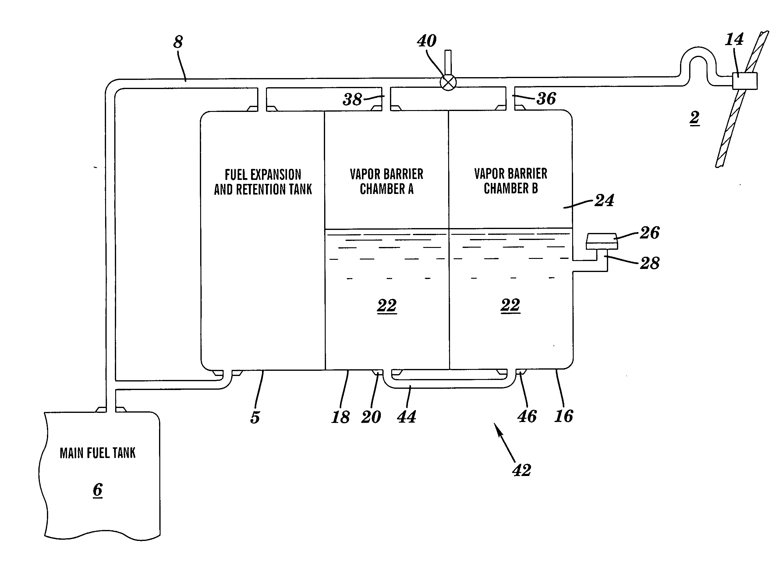
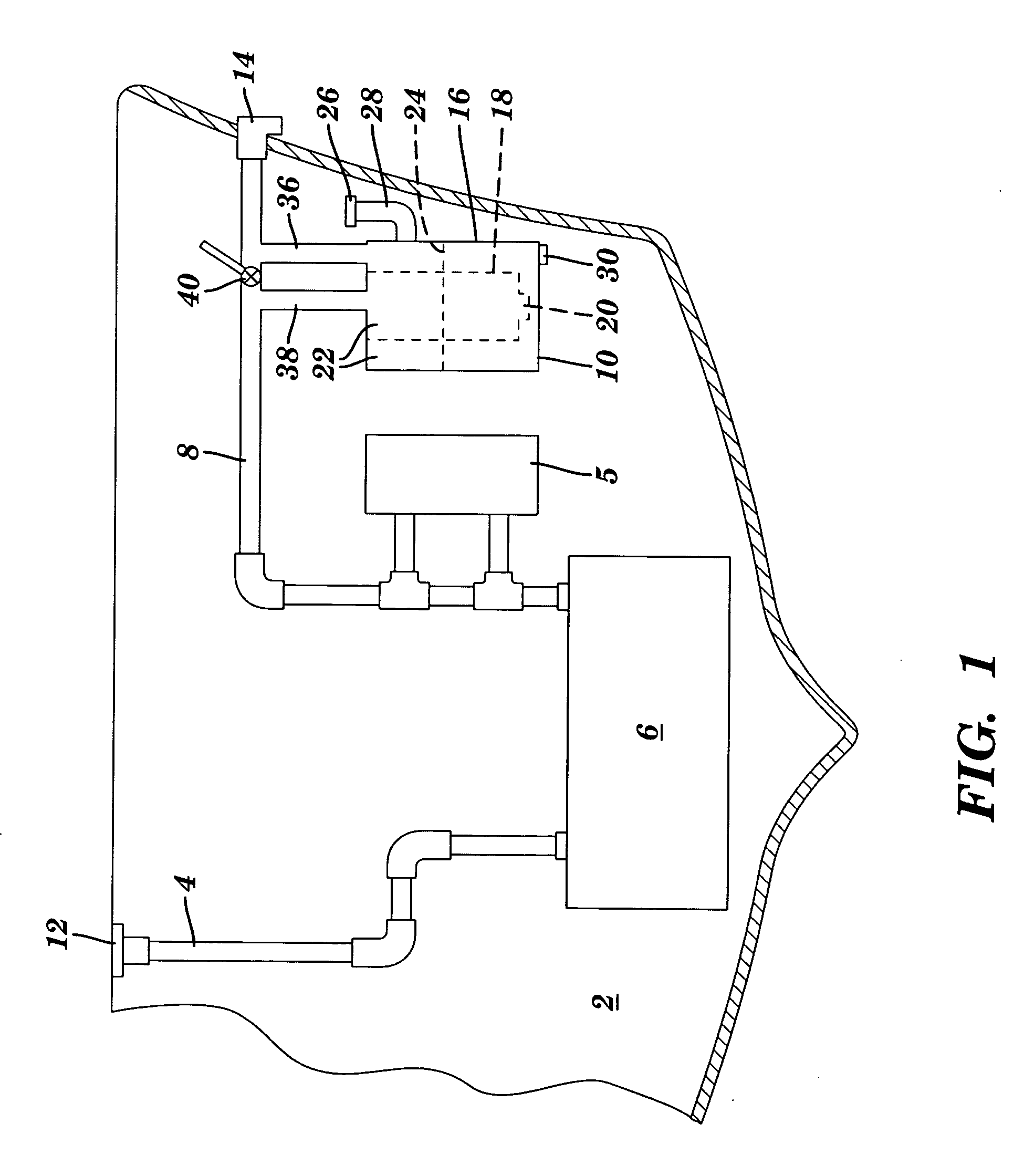
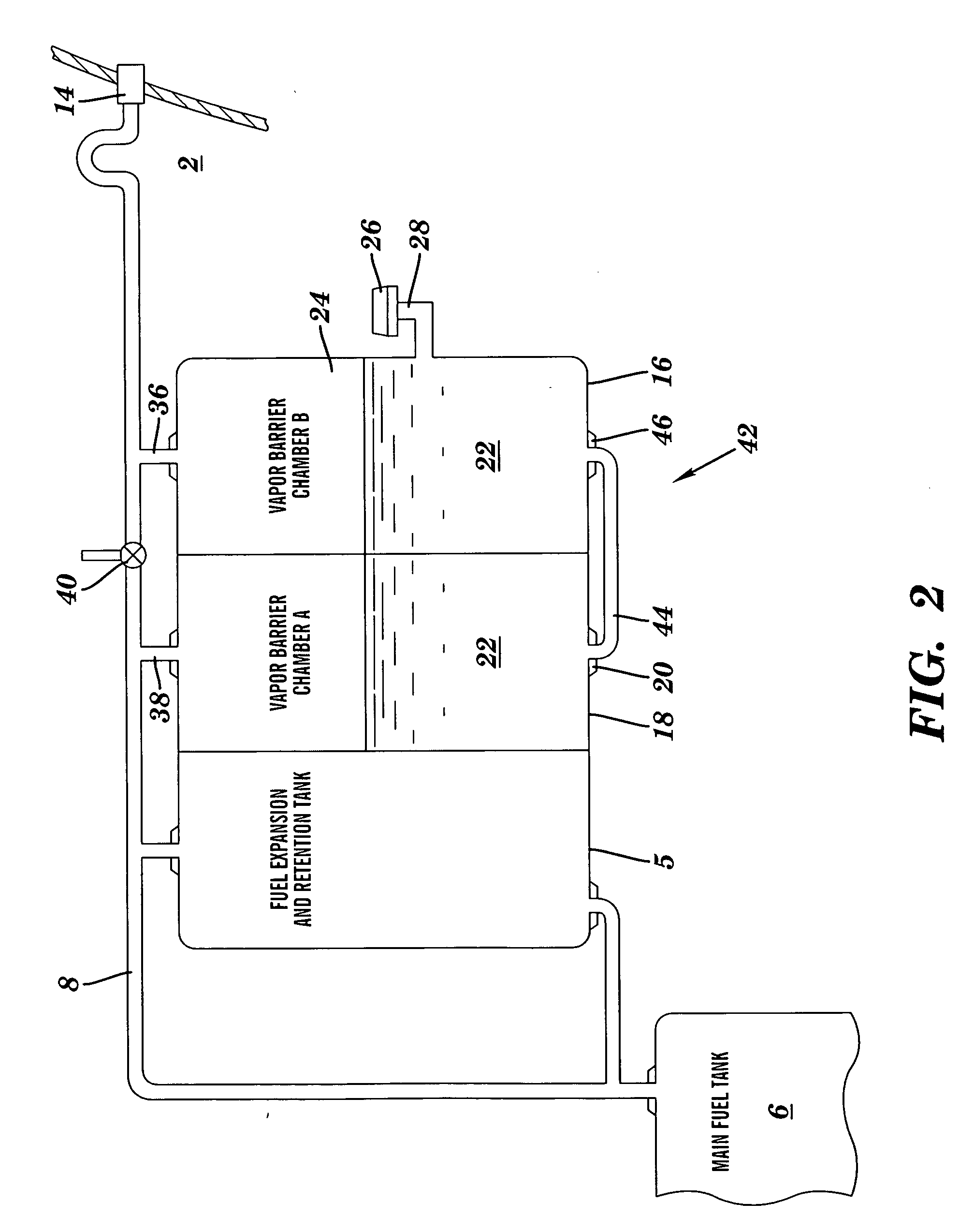
[0009] The above drawbacks and deficiencies are overcome or alleviated by A tank pressure compensation system including a chamber having a first end and a second end, the first end connectable to a fluid repository having a first fluid for fluid communication with the first end and the second end in fluid communication with the atmosphere. The chamber is receptive to a second fluid contained in a portion of the chamber intermediate the first and second ends disposed above a level of the second fluid, wherein the chamber allows displacement of the second fluid away from the first end toward the second end of the chamber when the first fluid expands while preventing flow of the first fluid into the atmosphere.
[0010] In one exemplary embodiment, a marine vessel fuel tank pressure compensation assembly for use in the hull of a marine vessel that has a fuel system including a fuel tank vented to a vent that communicates with the atmosphere is disclosed. The system includes a first chamber having a first lower portion and a first upper portion, the first upper portion configured for fluid communication with a first fluid disposed in the fuel tank via a fuel vent line; a second chamber having a second lower portion and a second upper portion, the second upper portion configured for fluid communication with the vent via a vent line, the second lower portion in fluid communication with the first lower portion of the first chamber; a barrier fluid disposed in at least a portion of the first chamber, the barrier fluid con

Problems solved by technology

If the tank were un-vented, increasing temperature of the fuel would cause fuel and vapor expansion that would cause the pressure in the tank to rise.
If the pressure became too high, the fuel tank could rupture, causing fire or explosion.
Wave action that rocks a boat can also cause fuel to be discharged overboard both during fueling and when the tank is full.
In addition, thermal expansion of the fuel due to an increase in fuel temperature may also cause either or both fuel

Method used


Image

  • System and method for tank pressure compensation
  • System and method for tank pressure compensation
  • System and method for tank pressure compensation

Examples


Embodiment Construction

[0023] Intent of the invention is to limit flow of a fluid from a tank into the atmosphere, and more particularly, limiting hydrocarbon emissions from fuel tanks. Temperature changes of fuel and fuel vapor cause a change in volume. Heating causes expansion of the fuel and fuel vapor resulting in the expulsion of fuel vapor from the fuel tank. Cooling of the fuel and fuel vapor causes a contraction of fuel and fuel vapor resulting in the induction of air into the tank. Air induction into the fuel tank creates additional fuel vapor.

[0024] Daily cycles of temperature change are referred to as diurnal cycles. The invention creates a barrier between the fuel vapor in the fuel tank and the atmosphere. Two tanks, or a single compartmented tank are filled to a little less than about ½ capacity with a fluid, such as oil. The oil can move between the two chambers allowing for volume changes in the fuel tank while preventing outside air and fuel tank vapors from mixing.

[0025] By displacing t...


PUM


Abstract

A supplemental fluid tank, preferably having two chambers each partially containing a fluid, fluid communicated intermediate a fuel tank and vent to reduce fuel vapor emissions, particularly for a boat. More specifically, when fuel is used or cooled, pressure or volume, respectively, of the remaining fuel in the fuel tank is reduced in prior art systems. Accordingly, air is drawn into the fuel tank through the vent line and becomes saturated with fuel (i.e., fuel vapor). Conversely, when fuel in the fuel tank is warmed it expands and fuel vapor is forced out of the vent into the environment. An exemplary embodiment reduces entry of air in through the vent and escape of fuel vapor out of the vent using two intermediate chambers in fluid communication with each other, each preferably having a non-evaporative fluid (e.g., oil), to provide volume/pressure compensation of the fuel in the fuel tank.

Description

CROSS REFERNCE TO RELATED APPLICATION [0001] This application claims the benefit of U.S. Provisional Application No. 60 / 553,039, filed Mar. 12, 2004 the contents of which are incorporated by reference herein in their entirety.BACKGROUND OF THE INVENTION [0002] This invention relates generally to a system and method for tank pressure compensation and specifically to a system and method for fuel tank pressure compensation for an internal combustion engine and, more particularly, this invention relates to a barrier tank assembly utilized to reduce diurnal emissions from a fuel tank, particularly in a marine vessel. [0003] Vehicles powered by internal combustion engines have at least one fuel tank that generally holds a supply of liquid fuel for the engine. The tanks are typically connected to a filler tube that is used to introduce fuel into the tank. The outer opening of the filler tube is usually covered with a removable cap. [0004] When fuel is added to the tank, it displaces the ai...

Claims


Application Information

Patent Timeline
IPC IPC(8): B60K15/03F02M25/08F02M37/20
CPCF02M37/20F02M25/08Y10T137/86324
Inventor VAITSES, STEPHEN P.
Owner VAITSES STEPHEN P
Why Eureka
Try Eureka