Method of forming a weld pad

Inactive Publication Date: 2005-09-15
WESTINGHOSE ELECTRIC CORP
View PDF10 Cites 19 Cited by
  • Summary
  • Abstract
  • Description
  • Claims
  • Application Information

AI Technical Summary

Benefits of technology

[0005] It is an object to provide a method of forming a weld pad that eliminates many of the steps of the previously employed prior art welding methods. It is an additional object of the present invention to provide a welding method that is enables faster installation than the prior art welding methods that have been employed.
[0006] With these objects in view, the present invention resides in a method of forming a weld pad between a surface of a pressure vessel having a penetration extending to the surface and a sleeve extending in the penetration, which comprises continuously forming a first weld layer that is attached to the sleeve and to the surface of the pre

Problems solved by technology

The sleeves extending through the external surfaces of pressure vessels and/or their welds may degrade as a result of micro-cracking, cracking, or other degradation/failure mechanisms during plant operation and/or plant transient conditions.
In some cases, small leaks have been detected in the sleeves extending through the heads of pressure vessels.
In addition, suspected flaws or defects may have developed during original fabrication.
Various full nozzle and partial nozzle (or “half nozzle”) welding repairs have

Method used


Image

  • Method of forming a weld pad
  • Method of forming a weld pad
  • Method of forming a weld pad

Examples


Example

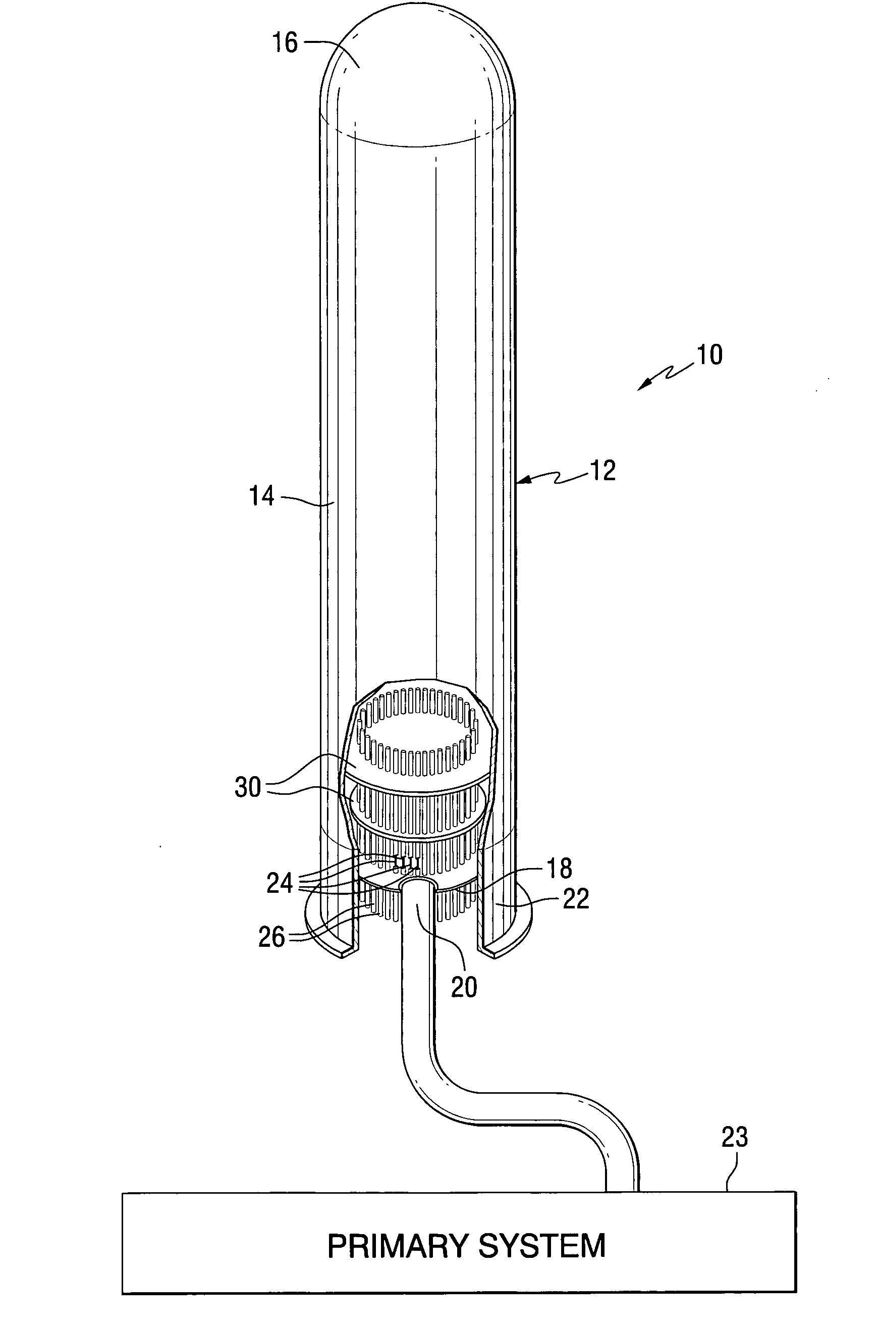
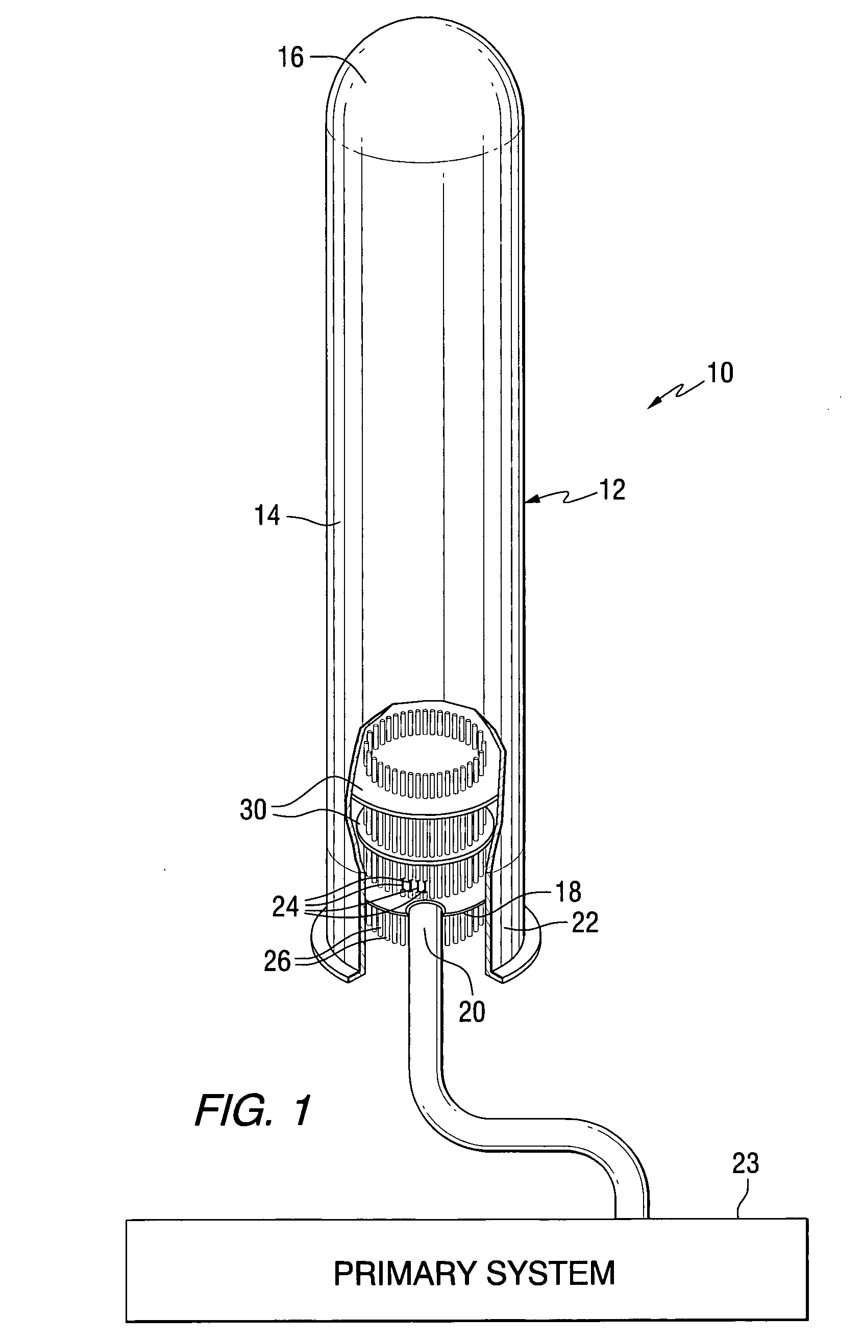
[0014] Referring now to the drawings in detail and in particular to FIG. 1, there is generally shown a pressure vessel 10 comprised of a shell 12 including a cylindrical body 14, a top head 16 and a bottom head 18 with a representative nozzle 20. The pressure vessel 10 generally has an inner surface 19 exposed to a contained fluid such as water, steam, air and other liquids and gases and an outer surface 21 exposed to ambient conditions of the local atmosphere. The heads 16 and 18 of pressure vessels may be welded to the cylindrical body 14 (as shown) or may be removably flanged to the cylindrical body 14 (not shown). As shown in FIG. 1, the pressure vessel 10 is vertically oriented and supported by a flanged skirt 22. Pressure vessels may also be oriented horizontally and may be supported by legs, pedestals, hangers or other means (not shown).

[0015] Because the present invention was made originally for repairing “pressurizer” vessels in pressurized water nuclear reactors for gener...


PUM

PropertyMeasurementUnit
Temperatureaaaaaaaaaa
Thicknessaaaaaaaaaa

Abstract

A weld pad is built up between a pressure vessel and a sleeve extending through a penetration in its surface by continuously forming one or more weld layers that are attached to the pressure vessel and the sleeve.

Description

CROSS REFERENCE [0001] This application for patent is a continuation of Provisional Patent Application No. 60 / 551,373 filed Mar. 9, 2004.BACKGROUND OF THE INVENTION [0002] The invention relates to method of forming a weld pad on a pressure vessel and more particularly to a method of forming a weld pad that comprises a part of a pressure boundary. The invention is particularly useful as a repair or as a preventative repair. As used herein: the term “pressure vessel” includes metallic process vessels, heat exchangers, piping, components and systems designed to contain fluids at pressures higher than 15 psig; the term “sleeves” includes metallic sleeves, tubes, nozzles and the parts of instrumentation and other appurtenances or items that extend into penetrations in the shells of pressure vessels; and the term “weld pad” means a built-up joint comprised of multiple layers of weld deposits. [0003] The sleeves extending through the external surfaces of pressure vessels and / or their welds...

Claims


Application Information

Patent Timeline
IPC IPC(8): B23K9/04
CPCB23K9/0043B23K9/044B23K9/125B23K2203/04B23K2201/04B23K2201/18B23K9/167B23K2101/04B23K2101/18B23K2103/04B23K2103/05
Inventor COE, KEITH E.NEWTON, BRUCE R.
Owner WESTINGHOSE ELECTRIC CORP
Why Eureka
Try Eureka