
Structural fire protection system

a structure and fire protection technology, applied in the direction of safes, movable spraying devices, constructions, etc., can solve the problems of inability to prevent or control fires, extreme danger to people living, and blazes that are too widespread to be controlled by any action, etc., to achieve convenient use, simple construction, and efficient operation

Inactive Publication Date: 2005-09-15
HEIL JOEL C +1
View PDF6 Cites 9 Cited by
  • Summary
  • Abstract
  • Description
  • Claims
  • Application Information

AI Technical Summary

Benefits of technology

"The invention is a fire protection system that is easy to build, operate, and modify for different structures and climatic conditions. It can be powered by electricity from a utility company or a battery system, and it has control systems that can be customized for each structure. The system has a large holding tank for water, which can be protected from extreme temperatures, and it has efficient means for collecting and returning water that has been sprayed. Overall, the invention provides a flexible and effective fire protection solution for various structures."

Problems solved by technology

For instance, we are aware of grass fires and even forest fires, in certain areas, like California, where the fire races rapidly across the dry grass and quickly consumes trees and unprotected structures, even causing extreme danger to people living there.
In such fires, the blaze is too widespread to be controllable by any action from a fire truck, either in anticipation of a blaze, or while a fire is consuming the structure, and particularly because there might be too many structures burning.
Fire involving a single structure might or might not be preventable or controllable by a single fire truck, but if there are several structures reacting to a grass fire or forest fire, any prevention or control would be impossible.
If there is no utility supply, those structures are at a great risk.
We have recognized that this might be necessary because it is always possible that a large grass fire might have already disabled the source of utility power.

Method used


Image

  • Structural fire protection system
  • Structural fire protection system
  • Structural fire protection system

Examples


Embodiment Construction

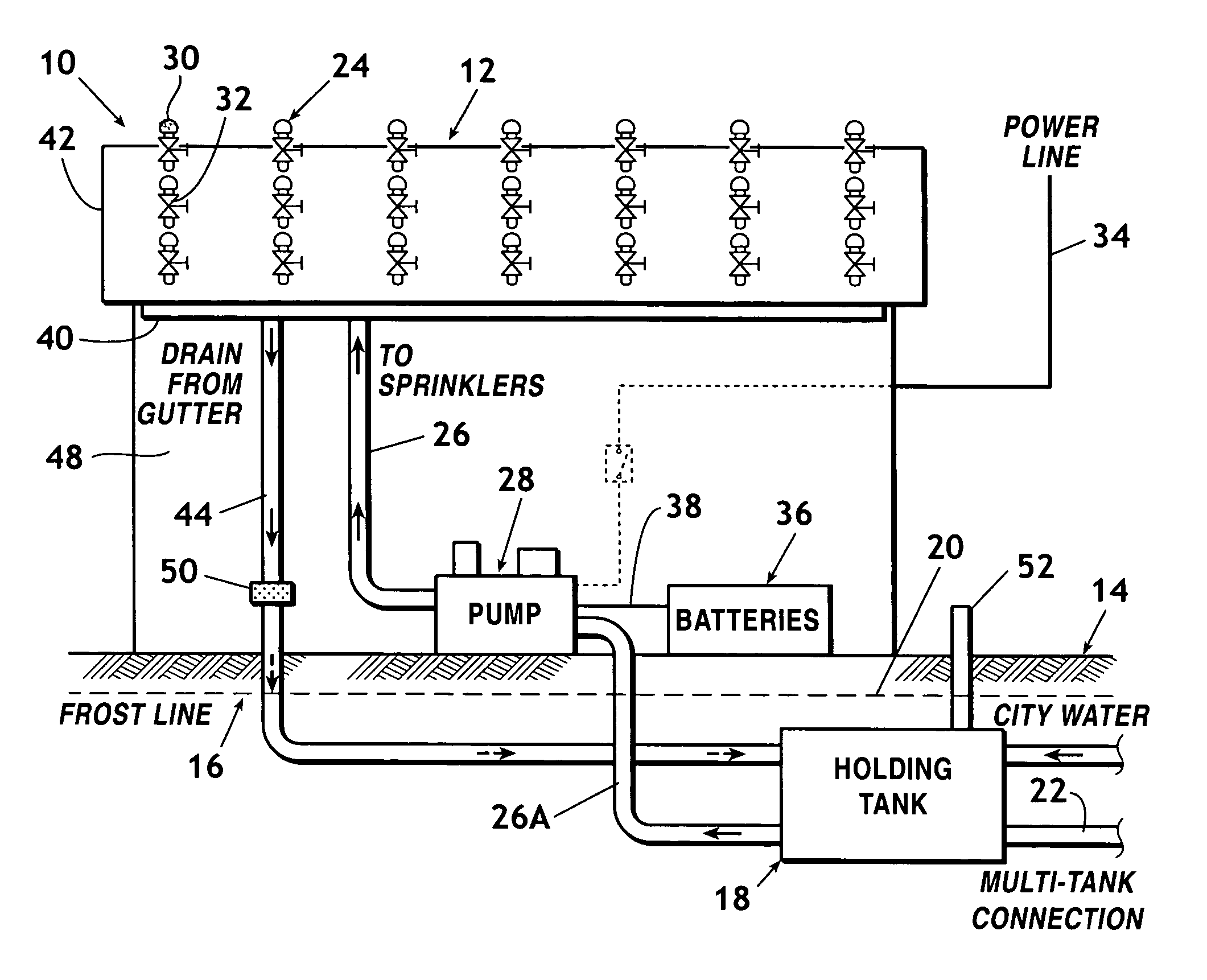
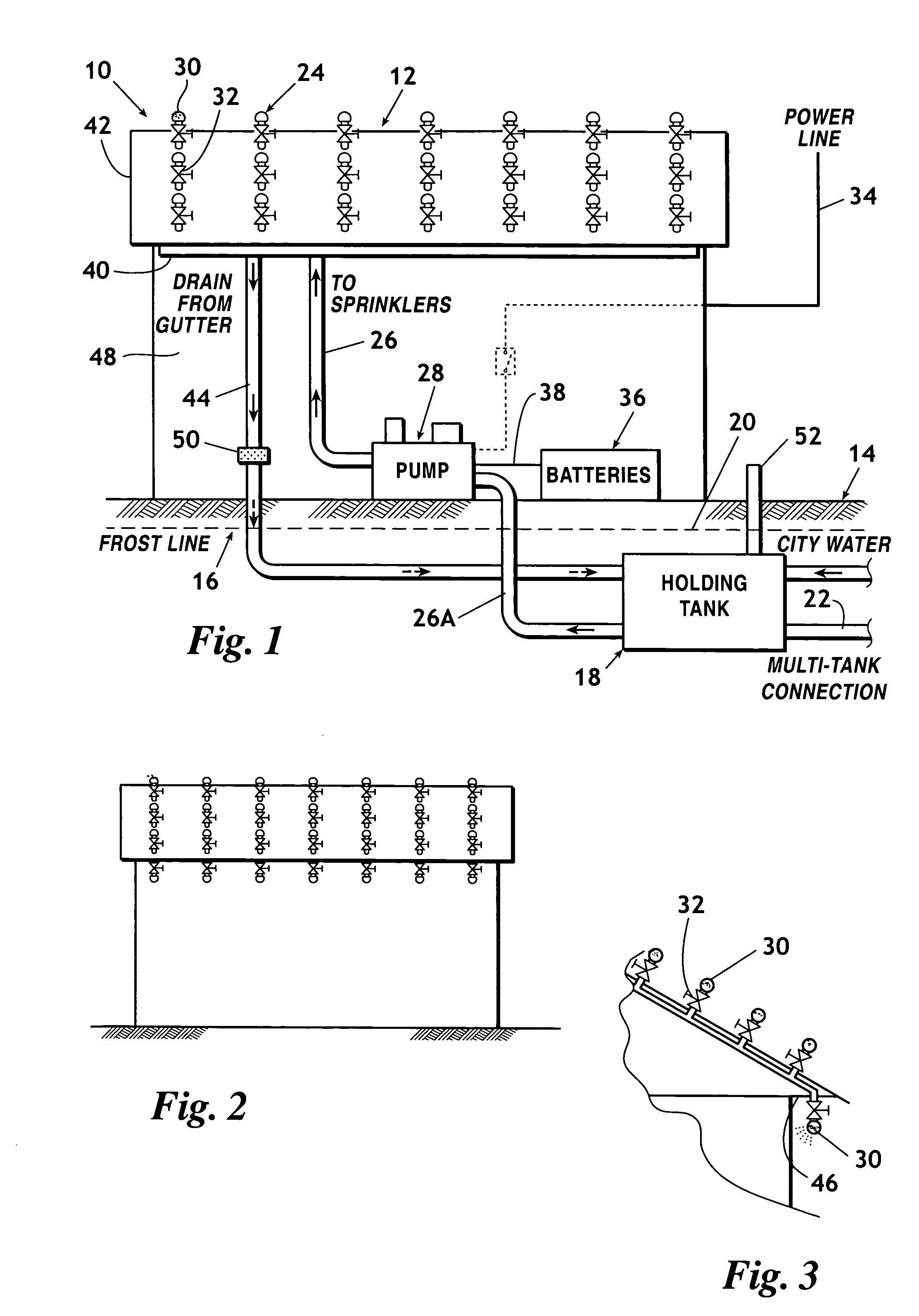
[0030] In FIG. 1 we describe a fire protection system 10, generally, as it would be interconnected with a typical building structure 12, generally, to provide fire protection to building structure 12, generally. In this situation, we are showing a fire protection system 10, generally, as it would be installed in a typical cold climate area with certain connections positioned underground, below earth 14 showing a frost line 16.

[0031] We have positioned a holding tank 18, generally, which receives a supply of water from a connection to a city utility water line 20, generally. We have calculated that for even a small structure, holding tank 18, generally, should be of at least 8,000 to 10,000 gallon capacity. Then, depending upon the size of any larger or more complex structure, holding tank 18 might have to be much larger, or the system might have to include additional holding tanks (not shown) as we indicate by showing a multi-tank connection 22.

[0032] As we explain in our descript...


PUM


Abstract

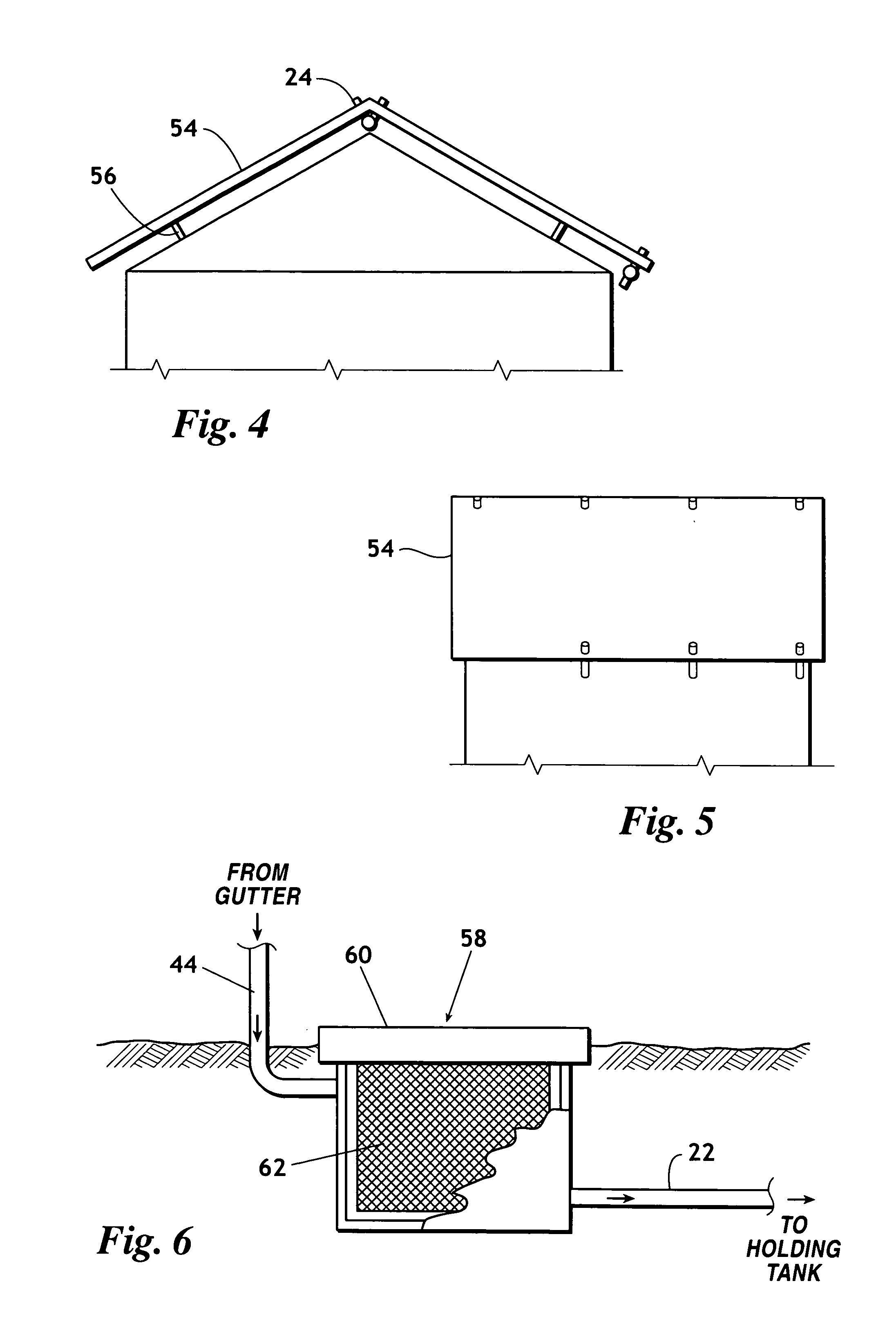
Our invention describes a fire protection system for a structure, such as a building, which may be operable as desired, or found necessary, by a building tenant, to protect against the possibility of a building fire or to extinguish a fire already occurring. Our system comprises a source of water which supplies water to a holding tank positioned near the structure, an electrically operable pump component connected to the holding tank and to a multiplicity of sprinkler members positioned at convenient locations on or in the structure. Sprinklers are intended to be mounted on the most convenient positions on the roof or sides of a building. Preferably, when mounted on the roof, sprinklers are to be connected to water supply lines positioned on the interior of the structure, when possible, for better appearance, and, for buildings having limited space below the roof, sprinklers are mounted on a fake ridge support system with water lines below the ridge system. Our system is developed to be made operable at the will of t4he tenant, or actuable automatically, or from a remote signal. The ultimate in fire protection is intended. The system includes proper inspection and clean-out components where needed for parts of the system

Description

FIELD OF THE INVENTION [0001] Our invention relates to fire protection systems. More particularly, our invention relates to fire protection systems which are adaptable for construction upon a structure to protect flammable material from fire damage by adequately spreading water over a structure. Still more particularly, our invention relates to fire protection systems which may be positioned upon a flammable structure upon which danger from fire damage would be most likely to occur. BACKGROUND OF THE INVENTION [0002] We have been in the construction business for many years and have never seen a fire protection system for a flammable structure, such as a domestic house, or even large warehouse, even remotely related to the type of protection system which we have developed. [0003] For instance, we are aware of grass fires and even forest fires, in certain areas, like California, where the fire races rapidly across the dry grass and quickly consumes trees and unprotected structures, ev...

Claims


Application Information

Patent Timeline
Patent Type & Authority Applications(United States)
IPC IPC(8): E05G1/00
CPCA62C35/58
Inventor HEIL, JOEL C.BAKER, BART T.
Owner HEIL JOEL C
Learn More