Digital video system using networked cameras

a video system and network camera technology, applied in the field of digital video systems using network cameras, can solve the problems of increasing the total cost of implementing such systems, introducing additional limitations, and requiring a large amount of equipmen

Inactive Publication Date: 2005-09-15
MARCHESE JOSEPH ROBERT
View PDF6 Cites 90 Cited by
  • Summary
  • Abstract
  • Description
  • Claims
  • Application Information

AI Technical Summary

Benefits of technology

[0015] In accordance with yet another aspect of the invention, there is provided a computer readable medium and method for use by a computer in recording a sequence of images, each of which comprises an individual image file in which the image is represented in a graphics file format that includes a first marker identifying the start of the image and a second marker identifying the end of the image. The computer readable medium includes a digital storage device containing a program that is operable to carry out the recording. The program stores the images together as a single file that comprises the group of images concatenated together in sequential order. The program is operable to index the file using the first and second markers. This index can then be used to provide quick access to individual images stored within the single file.

Problems solved by technology

Besides the limitations of a serial tape system, additional limitations are introduced when the sequencing rate of the multiplexer is too slow to allow sufficient video record / view speed of a given camera view.
Multiplexers are typically expensive and have limited expandability without purchasing additional complete systems.
Also, the configuration of these systems usually requires a skilled technician to be available at the systems site which increases the total cost of implementing such systems.
A factor limiting these digital systems is that an autonomous computer is required relatively near the video sources, sometimes with user intervention required at regular intervals.
The number of capture cards is limited to the specific design of the collecting equipment.
These systems are usually proprietary to a particular manufacturer and can be very expensive.
Remote viewing is usually not available.
Failover or redundancy function is also limited and expensive, due to the fact that the system is usually duplicated for redundancy.
As with the analog systems discussed above, these systems also have configuration requirements that typically require a skilled technician.
Although IP-based network cameras and camera servers have now evolved to a relatively advanced state, the use of a browser-based interface to this hardware has seemingly impeded development of user interfaces that provide simplified, automated control over the acquisition of snapshot and streaming images over the network.
While this may be handled easily enough for a single camera by bookmarking or pulling the URL out of the browser's history buffer, the task becomes more difficult when the user desires to change the access parameters or where different cameras need to be accessed.
Where the identified camera cannot be accessed, such as for example due to an improper address being specified, the user may simply receive a standard “404 not found” error message that is not helpful in diagnosing either the error or actual reason why access was not available.
Moreover, browser-based access is typically limited to either a snapshot mode or streaming images.
This results in relatively high network utilization that may be undesirable in a shared network environment.

Method used


Image

  • Digital video system using networked cameras
  • Digital video system using networked cameras
  • Digital video system using networked cameras

Examples


Embodiment Construction

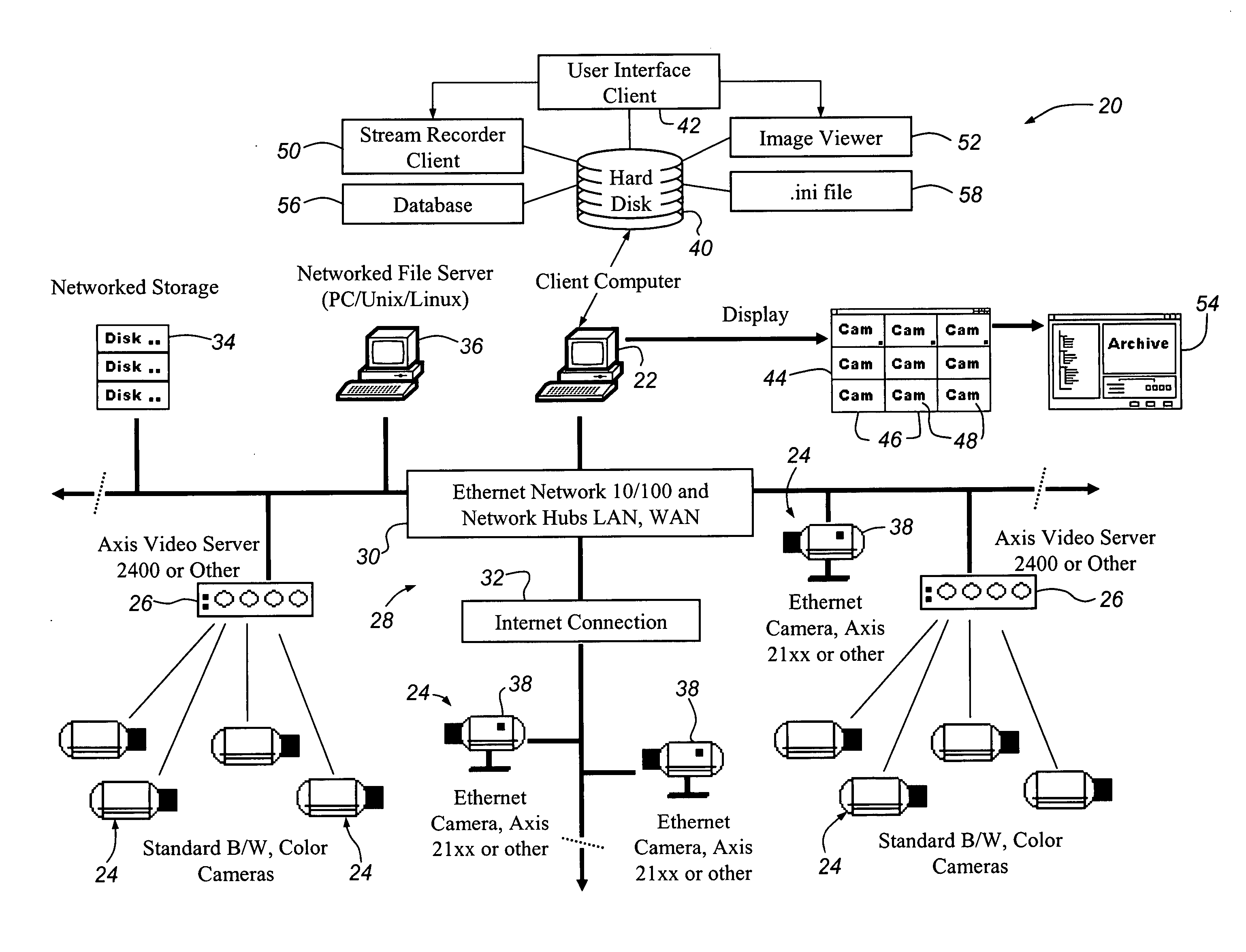
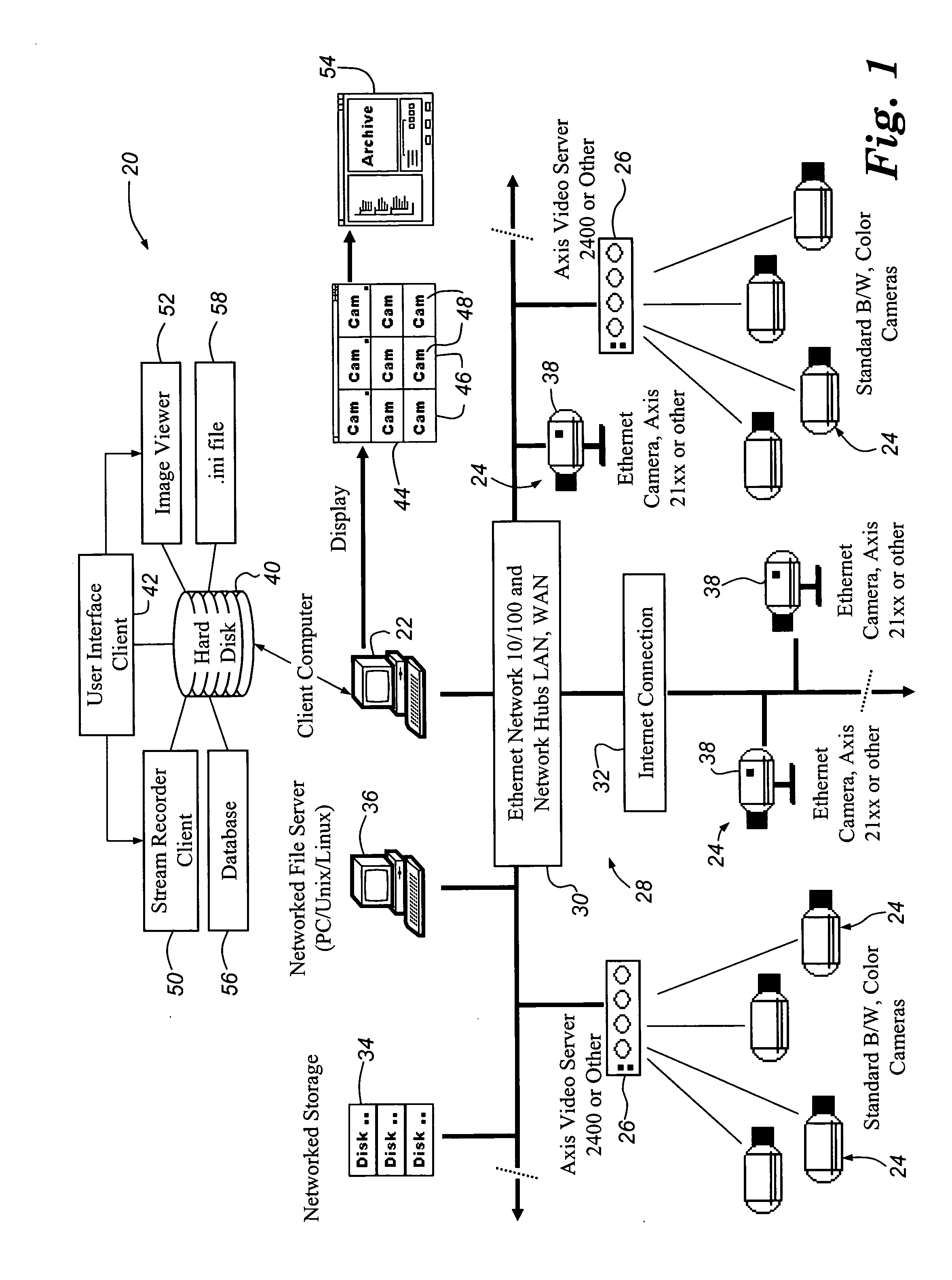
[0036] Referring to FIG. 1, there is shown a network setup of a digital video system 20 of the present invention. The video system 20 includes a client computer 22, a plurality of cameras 24, and one or more standalone video servers 26. The client computer is connected to the cameras 24 and video servers 26 via a network 28 which can include a private network segment 30 and a public network such as the Internet 32. Other networked components can be used such as a networked storage device 34 and a networked file server 36. Some of the cameras 24 comprise camera servers 38 which include both a video server and camera in a single integrated unit. The camera servers 38 can be, for example, Axis™ 200, 200+, or 2100 Ethernet cameras, available from Axis Communications Inc., Chelmsford, Mass. (www.axis.com). The video servers 26 can be Axis™ 2400, 2401, or 240 video servers, also available from Axis Communications, Inc. The cameras 24 that are connected to the video servers 26 can be indus...


PUM


Abstract

A digital video system including a computer connected via a network to a number of video servers and cameras. The computer includes a program that provides a grid of display windows, each of which displays an image received from the camera associated with that window. The program sequentially polls each camera, accessing and displaying an image from the camera in its associated window. The program can access the cameras at different frame rates. The program stores image streams in a single file, concatenating each successive image onto the end of the file. The file is then indexed using SOI and EOI markers to permit fast access to individual images within the file. The program can monitor received video and automatically start recording upon detecting motion within the video stream. Motion detection is implemented by comparing color component values for pixels from different images.

Description

CROSS-REFERENCE TO RELATED APPLICATION [0001] This application is a continuation of U.S. application Ser. No. 09 / 808,543, filed Mar. 14, 2001, now U.S. Pat. No. ______, which claims the priority of U.S. Provisional Application Ser. No. 60 / 189,162, filed Mar. 14, 2000. The entire disclosure of U.S. application Ser. No. 09 / 808,543 is hereby incorporated by reference.TECHNICAL FIELD [0002] This invention relates to systems for accessing, recording, and displaying camera images from any of a number of remotely located cameras and, more particularly, to such systems that provide access to images from one or more remote cameras over a public or private computer network. BACKGROUND OF THE INVENTION [0003] With the continuing expansion and availability of public and private computer networks it is becoming increasingly common to use these networks for remote video and image surveillance. Historically, analog systems have been used for CCTV systems for purposes such as surveillance. They inc...

Claims


Application Information

Patent Timeline
Patent Type & Authority Applications(United States)
IPC IPC(8): G06F17/30G09G5/14H04L29/06H04N5/77H04N5/92H04N7/16H04N7/18H04N7/24H04N21/2187H04N21/2343H04N21/61H04N21/81
CPCG06F17/3025H04L65/4092G08B13/19604G08B13/19606G08B13/19645G08B13/19656G08B13/19673G08B13/1968G08B13/19693G09G5/14H04L29/06027H04N5/77H04N5/9205H04N7/181H04N21/2187H04N21/234381H04N21/6175H04N21/816G06F17/30781G06F16/70G06F16/5838H04L65/613H04N23/661H04N23/631H04N23/695H04L65/1101H04L41/0654H04L41/0677H04L67/125
Inventor MARCHESE, JOSEPH ROBERT
Owner MARCHESE JOSEPH ROBERT
Why Eureka
Try Eureka