

Lighting apparatus
- Summary
- Abstract
- Description
- Claims
- Application Information
AI Technical Summary
Benefits of technology
Problems solved by technology
Method used
Image

Examples
second embodiment
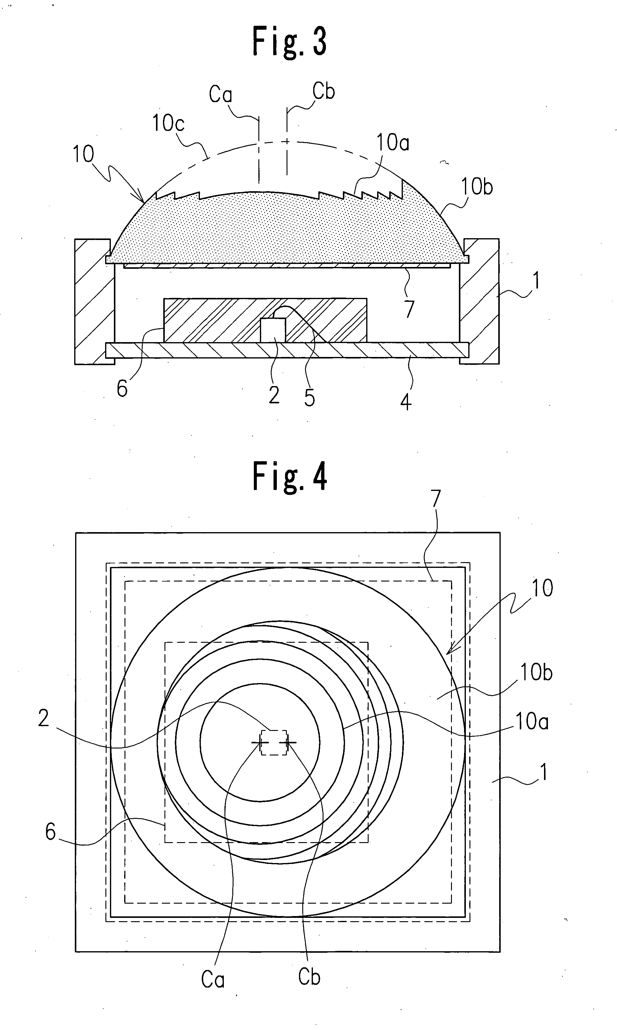
[0037]FIGS. 3 and 4 illustrate the lighting apparatus according to the present invention.
[0038] The lighting apparatus in the second embodiment is the same as the first embodiment in the basic structure and the operation, but it includes a lens 10 having a structure slightly different from that of the lens 3. The lens 10 has a Fresnel lens surface 10a provided on a central part of the lens and a smoothed lens surface 10b provided on a peripheral part of the lens, similarly as the lens 3. However, the lens 10 differs from the lens 3 in that a central axis or optical axis Ca of the Fresnel lens surface 10a deviates slightly from a central axis or optical axis Cb of the lens surface 10b corresponding to a portion of a virtual lens surface 10c. In addition, a central axis of an emission surface of the light source or LED deviates from the central axes Ca and Cb of the Fresnel lens surface 10a and the lens surface 10b. Alternatively, the central axis of the emission surface may be arrang...
third embodiment
[0040]FIGS. 5 and 6 illustrate the lighting apparatus according to the present invention.
[0041] A plurality of lighting mechanisms 20, which are arranged in a planar state, are used in the embodiment. Each of the lighting mechanisms 20 has a structure similar to the lighting apparatus in the first embodiment as shown in FIG. 1. The number of the lighting mechanisms is optionally determined. Lenses 21 in each of the plurality of lighting mechanisms 20 are formed integrally with respect to each other to form a lens assembly. The lens assembly is supported on the support 22. Each lens 21 has a Fresnel lens surface 20a and a lens surface 20b, similarly to the lens 3. A half-mirror film 23 is provided on a lower surface of the lens assembly of the lenses 21 throughout the whole of the lower surface. A lower surface of each of the lenses 21 forms a plane which faces chip-like LEDs, as light sources. These LEDs 24 are mounted on a larger substrate 25. In addition, the LEDs 24 are encapsula...
fourth embodiment
[0043]FIGS. 7 and 8 illustrate the lighting apparatus according to the present invention.
[0044] In the lighting apparatus shown in the embodiment, a plurality of LEDs 31R, 31G and 31B are disposed below one lens 30. The lens 30 has a Fresnel lens surface 30a and a lens surface 30b. In order to form mixed illumination light with three original colors of red, green and blue, for example, the LEDs 31R, 31G and 31B each emitting original color light are disposed close to each other and mounted on a substrate 32 (see FIG. 8). A half-mirror film 33 is provided on a lower surface of the lens 30. Meanwhile, a conical or pyramidal reflecting surface 35 may be provided on the support 34 in the lighting apparatus in order to employ light-emission in all directions effectively. A surface treatment increasing a reflection coefficient is provided on the reflecting surface 35.
[0045] In the embodiment, a structure in which the sealing member 36 for sealing the LEDs 31R, 31G and 31B does not includ...
PUM
 Abstract
Description
Claims
Application Information