Diagnosis of embedded, wireless mesh networks with real-time, flexible, location-specific signaling

a wireless mesh network and wireless mesh technology, applied in the field of data processing system protection, can solve the problems of never providing policy control on a mesh network, no provision in the prior art for flexible, location-specific diagnosis of wireless mesh networks,

Inactive Publication Date: 2005-09-15
PEIKARI CYRUS
View PDF3 Cites 338 Cited by
  • Summary
  • Abstract
  • Description
  • Claims
  • Application Information

AI Technical Summary

Benefits of technology

[0067] In a second embodiment of the preferred invention, the current invention allows for more “specificity of action.” In other words, instead of completely quarantining the infected node, the system can be configured to quarantine only certain aspects of the infection (such as blocking a certain communication port from the infected node) and to signal other nodes in the wireless mesh network to do the same.

Problems solved by technology

In addition, the prior art has no provision for flexible, location-specific diagnosis of wireless mesh networks.
Furthermore, the prior art has never provided for policy control on a mesh network, without using some sort of centralized policy controller such as a server.

Method used


Image

  • Diagnosis of embedded, wireless mesh networks with real-time, flexible, location-specific signaling
  • Diagnosis of embedded, wireless mesh networks with real-time, flexible, location-specific signaling

Examples


Embodiment Construction

[0084] The operation of the present invention will now be described in conjunction with the Drawing Figure.

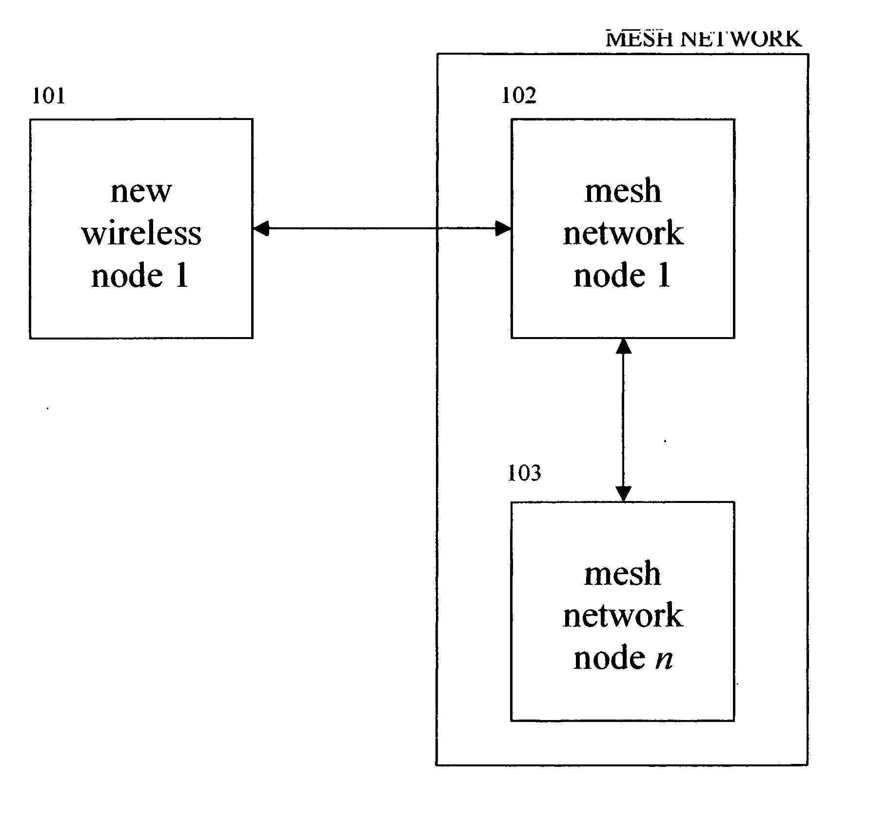
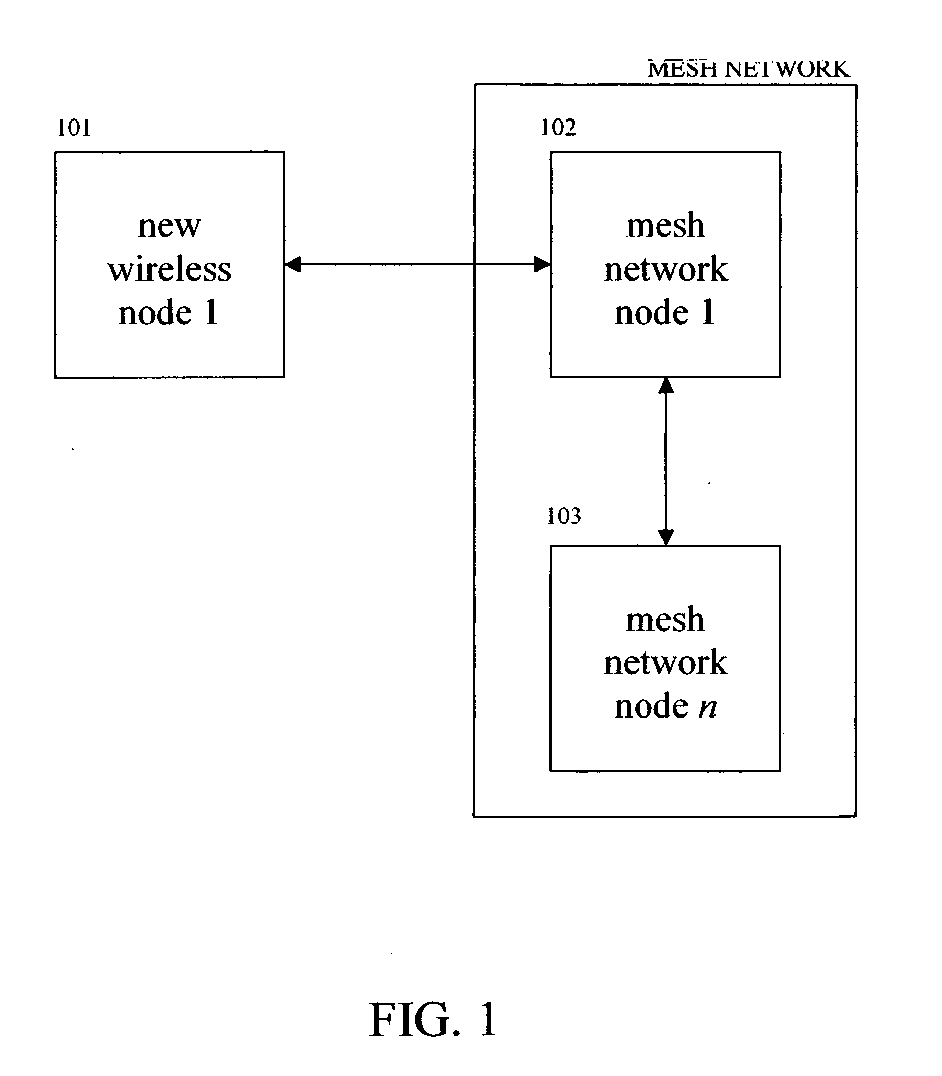
[0085]FIG. 1 is a flow diagram illustrating an embodiment of the present invention, which protects wireless mesh networks.

[0086] Step 101 represents a new node that attempts to authenticate to the nearest part of the existing mesh network at step 102 over a radio frequency (RF) connection. When the new node at step 101 attempts to connect to one of the existing nodes at step 102, the protection mechanism automatically begins. The existing node at step 102 first checks to see if the new node at step 101 has updated its security, including an updated virus scanner, firewall, vendor patches, etc.

[0087] If the new node at step 101 does not have updated security, then the node at 102 automatically quarantines it until it is updated. The node at 102 can also optionally provide the node at 101 with the information or files needed to update.

[0088] Once the new node at step 101 is u...


PUM


Abstract

A system for optimizing the security of data communication on wireless mesh networks invention uses existing mesh network nodes to control new nodes that attempt to join the network. In a preferred embodiment, this is achieved by (1) testing that a new node is “clean” before allowing it to join the wireless mesh network by scanning the new node for viruses, checking for security patches, etc., (2) quarantining an “infected” node from joining the wireless mesh network until it is cleaned, (3) signaling other nodes in the existing mesh network that a node is either “infected” or “clean”, (4) cleaning a new node by supplying it with antivirus software, vendor patches, etc. from nearby nodes in the existing wireless mesh network, (5) updating the wireless mesh network in real time with a list of clean and infected nodes, and (6) performing the above steps without the need for a central, controlling server.

Description

REFERENCES [0001] U.S. patents: [0002] U.S. Pat. No. 5,842,002 [0003] Schnurer, et al. [0004] Computer virus trap [0005] Nov. 24, 1998 [0006] U.S. Pat. No. 5,398,196 [0007] Chambers [0008] Method and apparatus for detection of computer viruses [0009] Mar. 14, 1995 [0010] U.S. Pat. No. 5,379,414 [0011] Adams [0012] Systems and methods for FDC error detection and prevention [0013] Jan. 3, 1995 [0014] U.S. Pat. No. 5,278,901 [0015] Shieh, et al [0016] Pattern-oriented intrusion-detection system and method [0017] Jan. 11, 1994 [0018] U.S. Pat. No. 5,121,345 [0019] Lentz [0020] System and method for protecting integrity of computer data and software [0021] Jun. 9, 1992 U.S. patent applications: [0022] 20030033536 [0023] Pak, Michael C.; et al [0024] Virus scanning on thin client devices using programmable assembly language [0025] Feb. 13, 2003 [0026] 20020083334 [0027] Rogers, Antony John; et al. [0028] Detection of viral code using emulation of operating system functions [0029] Jun. 27...

Claims


Application Information

Patent Timeline
Patent Type & Authority Applications(United States)
IPC IPC(8): H04L12/28
CPCH04L63/145H04W84/18H04W12/12H04W12/128
Inventor PEIKARI, CYRUS
Owner PEIKARI CYRUS
Why Eureka
Try Eureka