Interworking network maps of network management and element management systems

a network management and element management technology, applied in the field of communication networks, can solve the problems of affecting the efficiency of the affecting and requiring large-scale bandwidth requests, so as to achieve the effect of improving the efficiency of the operator at managing the communication network

Inactive Publication Date: 2005-09-15
WSOU INVESTMENTS LLC
View PDF22 Cites 66 Cited by
  • Summary
  • Abstract
  • Description
  • Claims
  • Application Information

AI Technical Summary

Benefits of technology

[0017] Advantageously, the invention enables improved operator efficiency at managing a communication network, particularly at keeping the NMS and EMS in synchronization.

Problems solved by technology

Still further, network customers demand fast response to any service request: a corporate user of bandwidth which requests additional capacity will be severely hampered if the response is not prompt.
As the number of EMS's in a network increases, it is a challenge to keep the NMS and EMS's in synchronization regarding the network topology.
This is however extremely time-consuming and cumbersome, not to mention error-prone for even the smallest changes or reorganizations in the hierarchy, or the naming of the node groups in the hierarchy.
For example, if each node's location in the node hierarchy on the NMS map is used to generate the location identifier of that node on the EMS map, then changing a group name is a complex task because a group may include dozen of network elements, and the name change requires changing the EMS location identifier of each NE in the group.
Map alignment is particularly challenging for EMS's that manage subscriber access systems; such an EMS can manage hundreds of subscriber access multiplexers (SAM).
However, this patent application does not disclose synchronization of NMS and EMS network views.

Method used


Image

  • Interworking network maps of network management and element management systems
  • Interworking network maps of network management and element management systems
  • Interworking network maps of network management and element management systems

Examples


Embodiment Construction

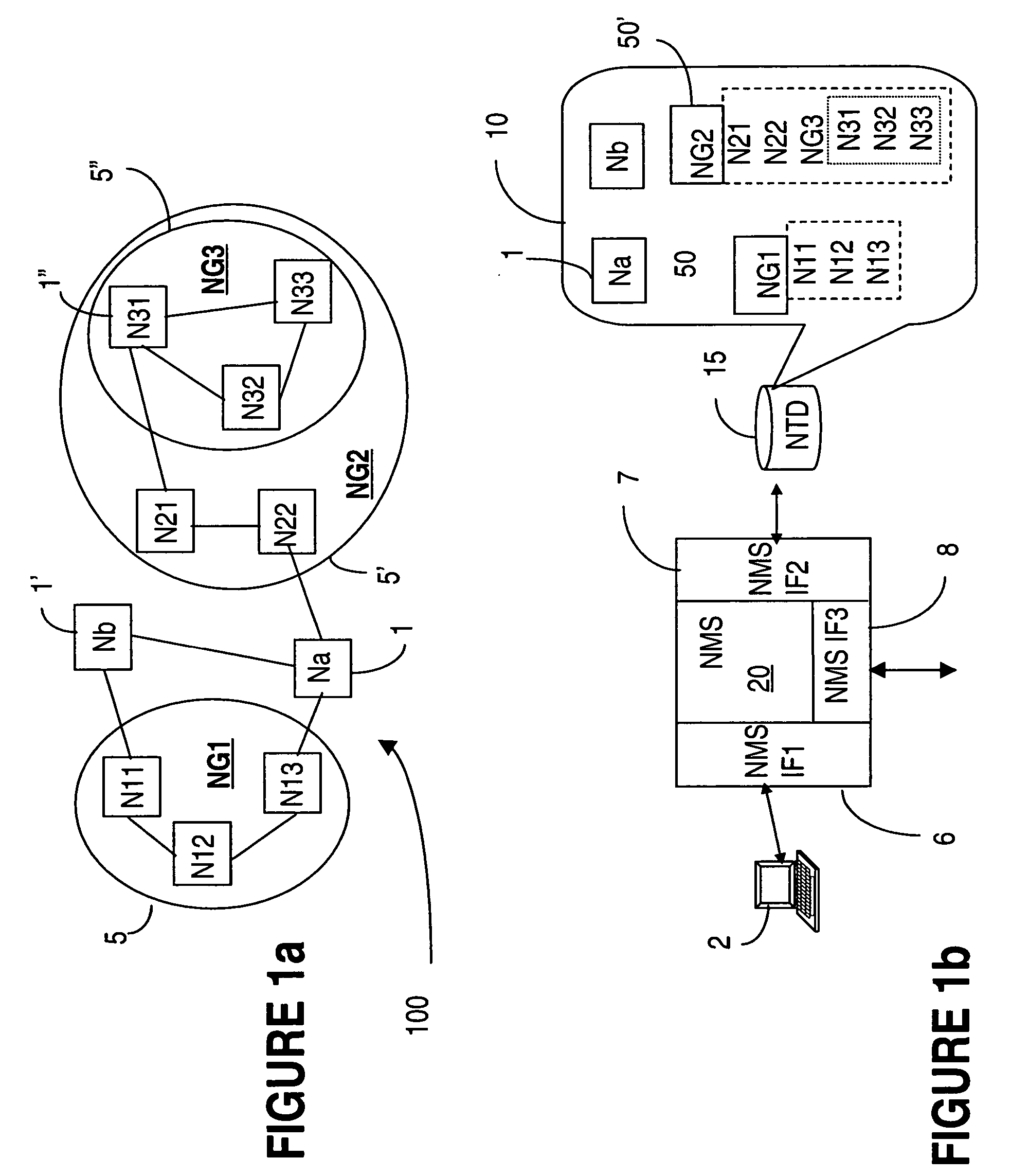
[0027]FIG. 1a shows an example of a communication network 100, illustrating a possible hierarchical grouping of the network nodes. In this example, network 100 includes nodes 1 (Na) and 1′ (Nb) and two node groups NG1, denoted with 5 and NG2, denoted with 5′. As indicated above, the nodes are grouped based on physical location or logical ordering, according to organizational rules used in the respective network. NG1 in this example includes nodes N11, N12 and N13. Nodes N21 and N22 are groups along with a node group NG3, denoted with 5″, into node group NG2. In turn, NG3 contains nodes N31, N32 and N33.

[0028]FIG. 1b shows a data terminal (a workstation) 2, with the network management system NMS 20 which enables network operator access for transmitting commands to the NMS and receiving information about operation of the network. The NMS 20 has a user interface 6 which performs well known functions, and which has additional functionality according to the invention. A graphical user i...


PUM


Abstract

In a communication network, the network management system NMS keeps one or more element management system EMS in synchronization of network topology changes using requests that are automatically generated or manually requested and then sent from the NMS to the affected EMS(s) whenever a node topology change is made at the NMS. Examples of changes are node creation, node move, node group move, node group renaming, etc. As the changes are completed in the EMS topology database, the EMS sends acknowledgments of the request to the NMS. This functionality requires verification of the validity of the request for that specific EMS, before the change is implemented at the NMS.

Description

FIELD OF THE INVENTION [0001] The invention is directed to communication networks and in particular to synchronizing the network map of the network management system (NMS) with that of an element management system (EMS). BACKGROUND OF THE INVENTION [0002] Communication networks are comprised of heterogeneous network elements (NE) such as telecommunication terminals, switches, routers, amplifiers, etc. interconnected in various configurations by physical hardware connections, and the software used to send, receive and route the information between these NEs. Network elements are each a complex programmable system, including programmable subsystems and local memory for storing the respective programs and maintaining records of the operating history. [0003] The current trend to integrate smaller networks of various technologies into global networks that extend over tens of thousands of miles, demands reliable and sophisticated tools for monitoring and controlling operation of a very la...

Claims


Application Information

Patent Timeline
Patent Type & Authority Applications(United States)
IPC IPC(8): H04L12/28
CPCH04L41/12H04L67/1095H04L45/42H04L41/22
Inventor RADI, TAREKGHADIE, CHADIE
Owner WSOU INVESTMENTS LLC
Why Eureka
Try Eureka