
Clutch device for a hydrostatic continously variable transmission

Inactive Publication Date: 2005-09-15
HONDA MOTOR CO LTD
View PDF4 Cites 9 Cited by
  • Summary
  • Abstract
  • Description
  • Claims
  • Application Information

AI Technical Summary

Benefits of technology

[0008] In view of the above problem, it is an object of the present invention to provide a clutch device for a hydrostatic continuously variable transmission which can transmit power stably by ensuring the control of the opening and closing operations of the clutch valve.
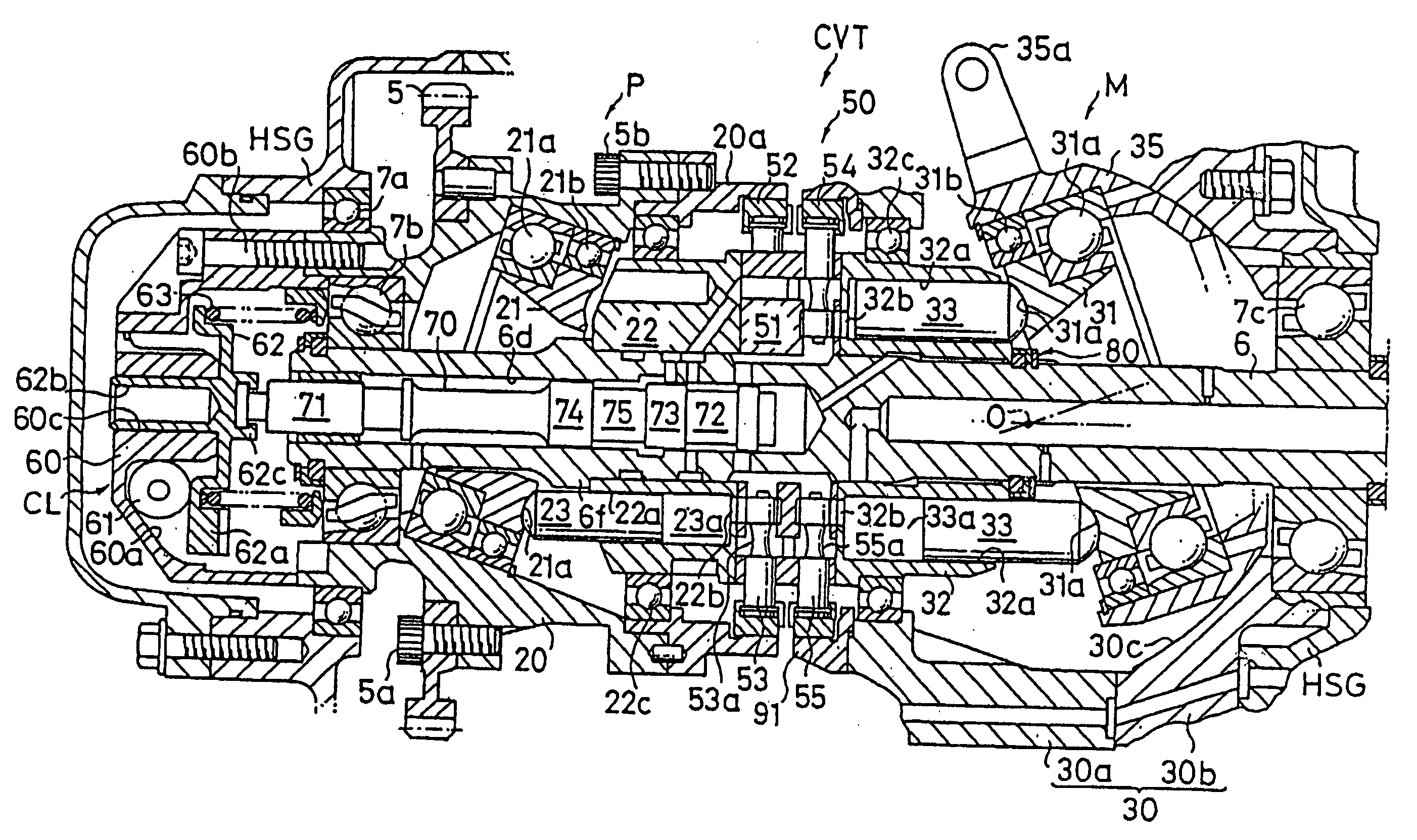
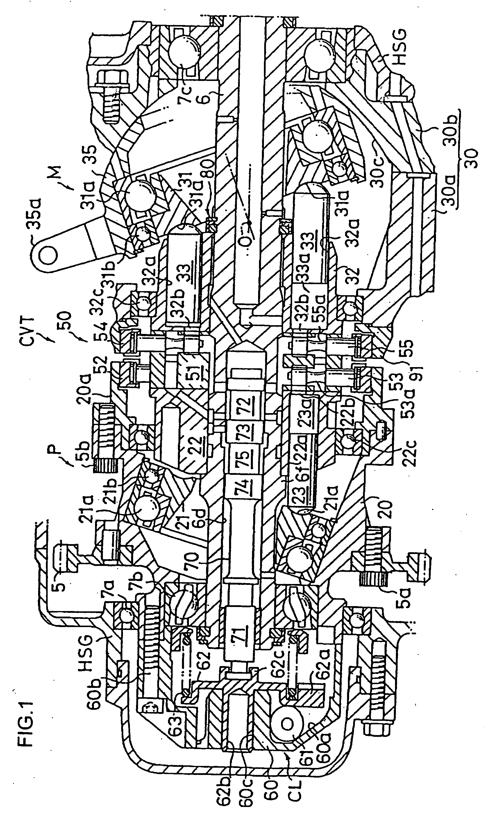
[0009] Therefore, the hydrostatic continuously variable transmission according to the present invention is constituted such that a hydraulic pump and a hydraulic motor are linked together by a hydraulic closed circuit, and the capacity of at least one of the hydraulic pump and the hydraulic motor is controlled to change the input rotation of the hydraulic pump and take it out as the output rotation of the hydraulic motor. The clutch device of the hydrostatic continuously variable transmission comprises a clutch valve for connecting and disconnecting a high pressure side oil passage and a low pressure side oil passage constituting the hydraulic closed circuit to control the transmission of rotation from the hydraulic pump to the hydraulic motor, a governor mechanism for generating governor force corresponding to the input rotation speed of the hydraulic pump using centrifugal force generated by the input rotation of the hydraulic pump and applying this governor force in the closing direction of the clutch valve, urging means for giving urging force in the opening direction of the clutch valve, and a buffer mechanism for easing the opening and closing movements of the clutch valve activated according to the governor force and the urging force.
[0011] Preferably, an oil passage having an orifice connected to the oil pool chamber is formed in the valve spool to discharge oil in the oil pool chamber therethrough so as to provide resistance to a change in the capacity of the variable oil chamber and ease the movement of the valve spool. Further preferably, the oil passage is formed in the valve spool in such a manner that it is open to a connection portion for connecting the governor mechanism and the valve spool.
[0012] In the clutch device of the present invention, when forces in the direction of disconnection and the direction of connection applied to the clutch valve compete with each other, the movement of the clutch valve caused by a change in governor force corresponding to a sudden rise in oil pressure and a change in input rotation due to the quick operation of the throttle is eased by the buffer mechanism to become slow, whereby the opening and closing control of the clutch valve is made reliable to transmit the output rotation of the engine for driving the hydraulic pump to the hydraulic motor stably.
[0013] When the clutch valve is constituted such that the valves pool is movably arranged in the spool hole and the buffer mechanism has the variable oil chamber surrounded by the inner wall of the spool hole and the outer wall of the valve spool and the oil pool chamber connected to the variable oil chamber in the valve spool, the buffer mechanism is arranged compact in the clutch valve, thereby making it possible to make the clutch valve compact and the continuously variable transmission compact as well.
[0014] In this constitution, when the oil passage having an orifice connected to the oil pool chamber is formed in the valve spool to discharge oil in the oil pool chamber so as to give resistance to a change in the capacity of the variable oil chamber, the opening and closing movement of the valve spool can be made more reliable and can be eased effectively. When the formed oil passage is open to the connection portion between the governor mechanism and the valve spool, the connection portion can be lubricated with working oil discharged through the oil passage.

Problems solved by technology

That is, when the opening and closing operations of the clutch valve are repeated, it is difficult to transmit power stably.

Method used


Image

  • Clutch device for a hydrostatic continously variable transmission
  • Clutch device for a hydrostatic continously variable transmission
  • Clutch device for a hydrostatic continously variable transmission

Examples


Embodiment Construction

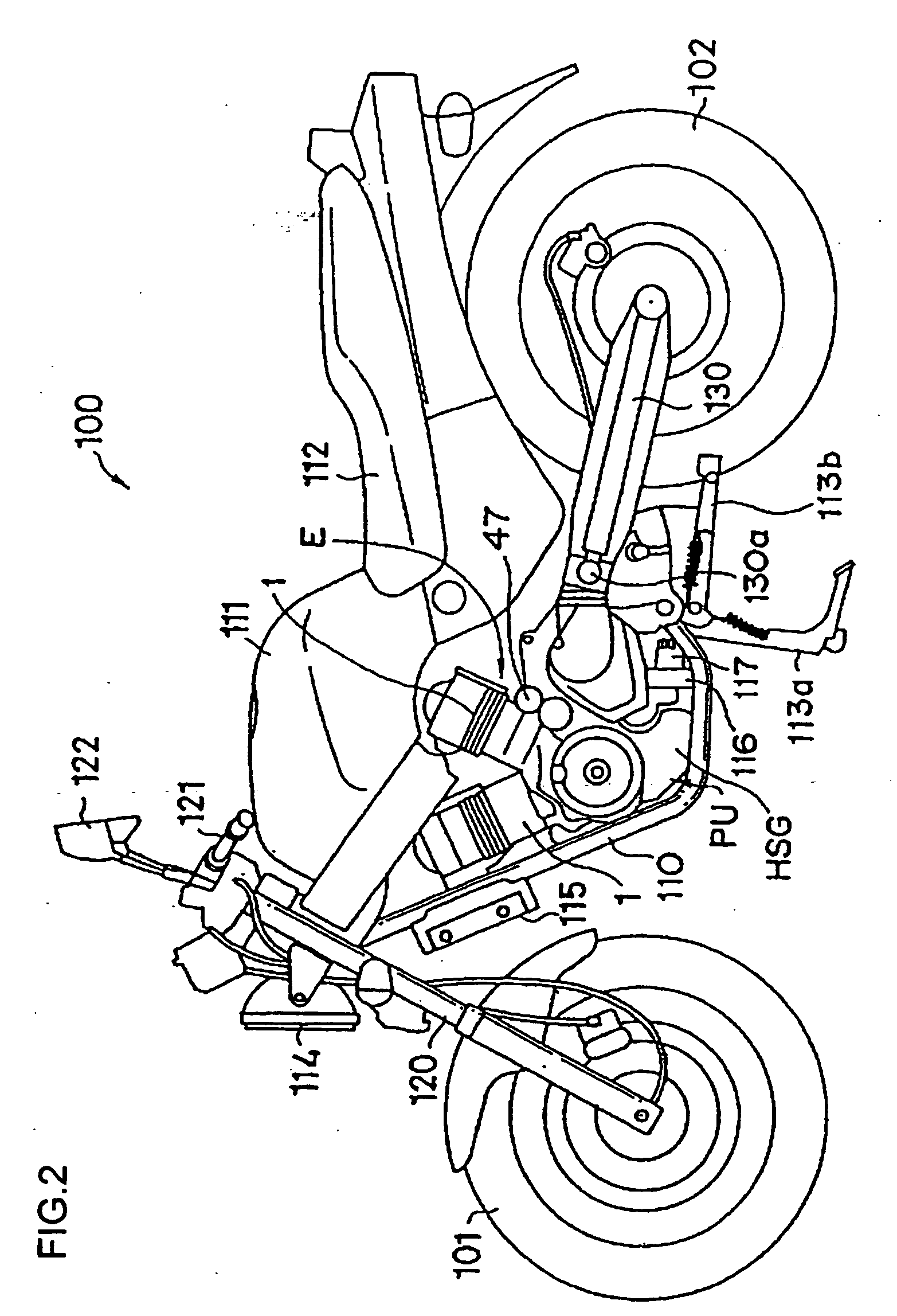
[0033] A preferred embodiment of the present invention will be described hereinunder with reference to the accompanying drawings. FIG. 2 shows the whole appearance of a motorcycle having the hydrostatic continuously variable transmission of the present invention. In FIG. 2, the internal structure of the motorcycle is exposed by removing part of the side cover member of the motorcycle. This motorcycle 100 comprises a main frame 110, a front fork 120 attached to the front end of the main frame 110 in such a manner that it can turn on the axis extending obliquely in the vertical direction, a front wheel 101 rotatably connected to the lower end of the front fork 110, a swing arm 130 pivotably connected to the rear of the main frame 110 with a shaft 130a as the center in such a manner that the swing arm 130 can swing in the vertical direction, and a rear wheel 102 rotatably connected to the rear end of the swing arm 130.

[0034] To the main frame 110 are mounted a fuel tank 111, a seat 11...


PUM


Abstract

In a hydrostatic continuously variable transmission, a hydraulic pump is linked to a hydraulic motor by a hydraulic closed circuit to change the capacity of the hydraulic motor so as to change the speed of a motorcycle continuously. A clutch device comprising a clutch valve for connecting and disconnecting a high pressure side oil passage and a low pressure side oil passage constituting the hydraulic closed circuit. A governor mechanism for generating governor force corresponding to the input rotation speed of the hydraulic pump and applying this governor force in the closing direction of the clutch valve. A spring for giving urging force in the opening direction of the clutch valve, and a buffer mechanism having a variable oil chamber and an oil pool chamber for easing the opening and closing movements of the clutch valve activated according to the governor force and the urging force.

Description

TECHNICAL FIELD [0001] The present invention relates to a hydrostatic continuously variable transmission in which a hydraulic pump and a hydraulic motor are linked together by a hydraulic closed circuit, and the capacity of at least one of the hydraulic pump and the hydraulic motor is controlled to change the input rotation of the hydraulic pump and take it out as the output rotation of the hydraulic motor. More specifically, it relates to a clutch device for connecting and disconnecting a high pressure side oil passage and a low pressure side oil passage constituting the hydraulic closed circuit in this hydrostatic continuously variable transmission. BACKGROUND OF THE INVENTION [0002] Various types of hydrostatic continuously variable transmissions have been known and implemented. For example, patent document 1, patent document 2 and patent document 3 proposed by the present applicant disclose a hydrostatic continuously variable transmission. This hydrostatic continuously variable ...

Claims


Application Information

Patent Timeline
IPC IPC(8): F16H39/00F16H39/14F16H61/40F16H61/4043
CPCF16H39/14Y10T477/6203F16H61/425
Inventor YOSHIDA, YOSHIHIROMITSUBORI, TOSHIMASAOZEKI, TAKASHINAKAMURA, KAZUHIKO
Owner HONDA MOTOR CO LTD
Learn More