Analysing nano-objects

a nano-object and nano-structure technology, applied in the field of nano-object analysis, can solve the problems of difficult experimental quantification of cross-section values, low contrast of current particle characterisation techniques, time-consuming and/or-high-cost, etc., and achieves high throughput particle analysis and ease of instrument operation. , the effect of convenient for a user

Active Publication Date: 2021-05-04
UNIV COLLEGE CARDIFF CONSULTANTS LTD
View PDF13 Cites 0 Cited by
  • Summary
  • Abstract
  • Description
  • Claims
  • Application Information

AI Technical Summary

Benefits of technology

[0065]In some examples, as noted above, the method may comprise immobilizing nano-objects on a substrate and moving the substrate relative to the imaging apparatus to acquire the plurality of images. For example, a substrate may be shifted laterally by approximately one or two optical resolutions, and the ratio of the shifted and unshifted image may provide an extinction image which may be analysed to analyse the particle-induced transmission change and in turn determine the extinction cross-section. This supresses longer range variations, but short-range roughness on the scale of the shift may be evident. The sample position can be modulated alternating between two or more shift values, so to avoid the effect of thermal drifts over long exposure times.
[0066]As also noted above, in other examples, the nano-objects are in suspension in a carrier fluid. Methods for measuring nano-objects in a fluid may be convenient for a user and may enable high throughput particle analysis. This could ease instrument operation, because chemically-grown nano-objects are generally supplied as a suspension or colloid, and immobilizing the nano-objects on a substrate requires further processing of the nano-objects in such cases. In some examples the contamination of fluids, e.g. water, with nanoparticles might be of interest. Moreover, in carrying out analysis methods, the substrate may be static while the nano-objects in suspension are subject to Brownian motion and movement of the nano-objects means that they move in and out of imaging pixels and / or focus and therefore ‘short range roughness’ as described above may be avoided. While the movement of the nano-objects provides advantages, significant and rapid shifts in position between images can complicate measurements. For example, particle tracking becomes complicated and individual nano-objects may move out of the field of view altogether. This may limit the time to acquire a signal and therefore analysis of faster moving nano-objects may suffer in terms of SNR.
[0070]To slow the movement of nano-objects, for example to prevent the nano-objects from moving too fast to allow simple tracking thereof, and / or from exiting an imaging frame between images, in some examples, the method may further comprise restricting the motion of nano-objects in suspension. This may comprise changing (for example, increasing) the viscosity of the carrier fluid, for example by changing the temperature thereof. For example, for some examples, cooling the carrier fluid may increase its viscosity. For example, a temperature may be controlled within a range of around 20 Kelvin, using a temperature control apparatus, such as a Peltier device.
[0078]In some examples, the method may comprise applying a singular value decomposition (SVD) to the plurality of images to compensate for imaging apparatus parameter drift, for example through use of an SVD filter. Such a filter identifies the drift associated with an imaging apparatus and allows it to be removed from a captured image. This may increase sensitivity and allow nano-objects of smaller size to be imaged than would otherwise be possible.

Problems solved by technology

However, for some types of samples, such techniques may suffer from low contrast.
However, current techniques for particle characterisation may be inaccurate, time consuming and / or expensive.
However, cross-section values—especially for scattering—can be difficult to quantify experimentally.
Currently available approaches tend to be complex and are generally suited to academic, rather than commercial, environments (an example may include laser-based techniques such as spatial modulation spectroscopy).
Some techniques, such as dark-field micro-spectroscopy, do not provide quantitative results and as such scattering cross-sections of nano-objects are rarely measured quantitatively and results are typically presented in arbitrary units.

Method used


Image

  • Analysing nano-objects
  • Analysing nano-objects
  • Analysing nano-objects

Examples


Embodiment Construction

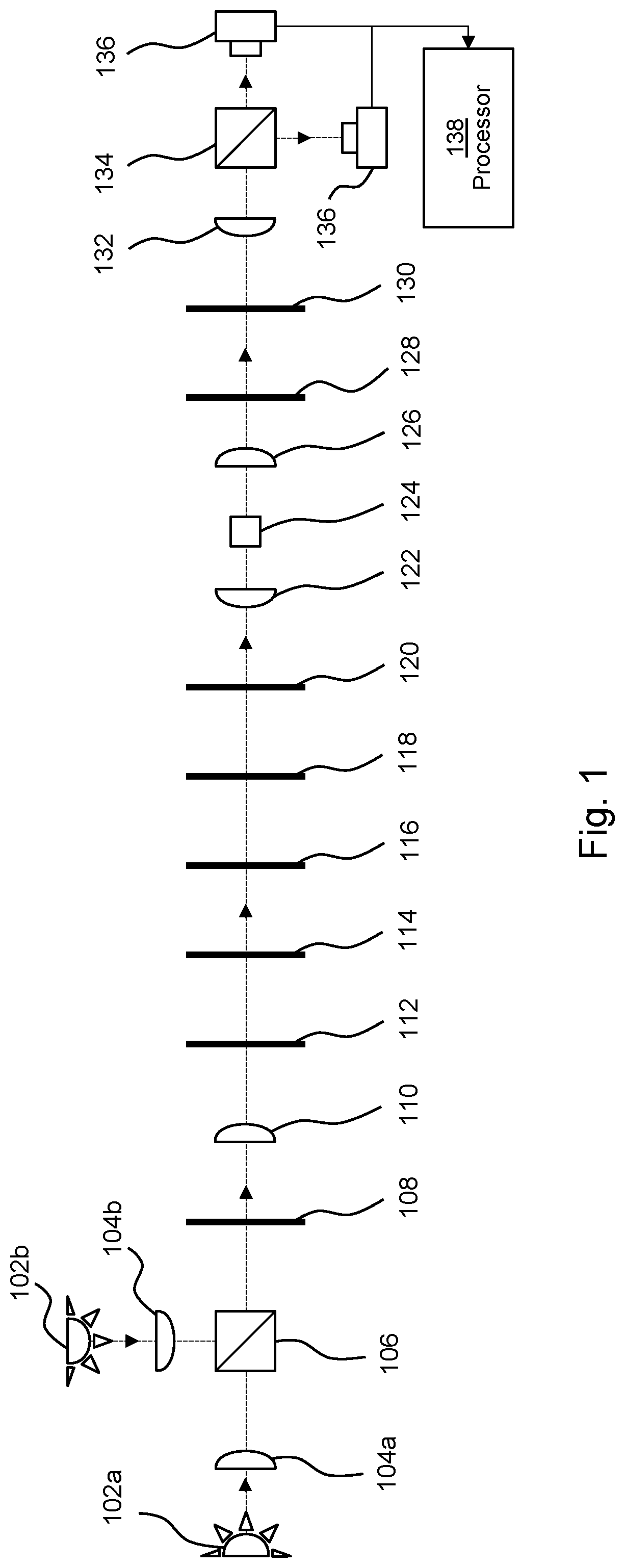
7]FIG. 1 is an example of a system which may be utilised in one embodiment of the present invention.

[0098]In this example, an illumination apparatus comprises a first and second light source 102a, 102b, which may for example comprise LEDs. The light sources 102 provide light via respective collector lenses 104a, 104b to a beam combiner 106, which in this example comprises a dichroic beam combiner. Light is projected via a diaphragm 108 which controls the illumination area onto the sample, a lens 110 and a first polariser 112 before being passed to a continuously variable spectral filter 114.

[0099]The light sources 102 may cover the full range allowed by the optics, for example they may provide wavelengths from 300 nm to 1500 nm. In some examples the light sources may be LEDs which may have a bandwidth from 30 nm to 300 nm.

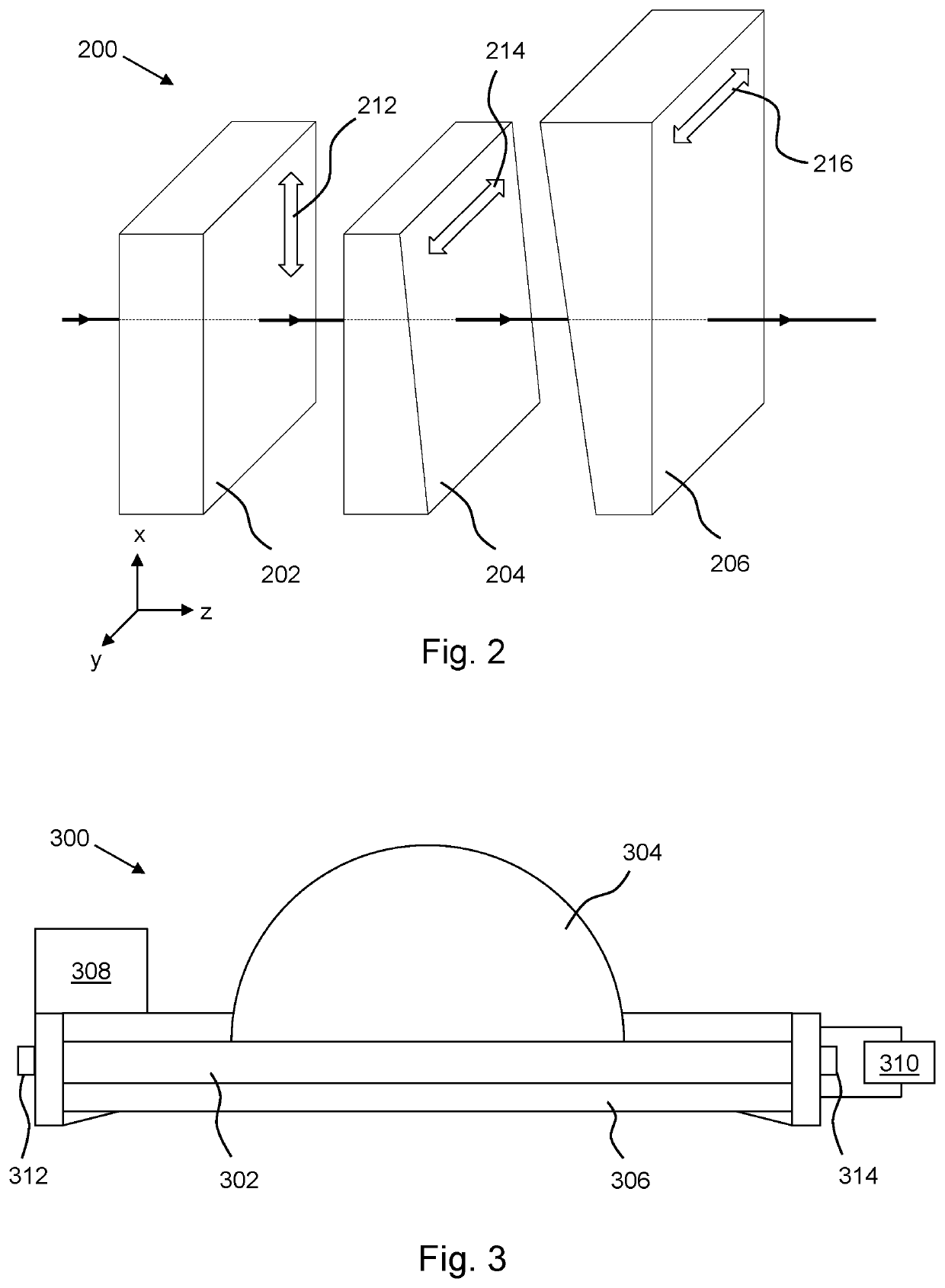
[0100]FIG. 2 is an example of a continuously spectral filter 200 which may be utilised as the continuously spectral filter 114 in one embodiment of the present inv...


PUM

PropertyMeasurementUnit
areaaaaaaaaaaa
diameteraaaaaaaaaa
diameteraaaaaaaaaa

Abstract

Methods and apparatus for analysis of nano-objects using wide-field bright field transmission techniques are described. Such methods may comprise acquiring a plurality of images of a sample comprising a plurality of nano-objects using bright field illumination via a continuously variable spectral filter, and identifying a nano-object within the sample in the plurality of images, wherein the position of the nano-object changes between images. Using data extracted from the plurality of images, an extinction cross-section of the identified nano-object may be quantitatively determined.

Description

FIELD OF INVENTION[0001]The present invention relates to methods of analysing nano-objects, in some examples using wide-field illumination techniques.BACKGROUND[0002]In some examples, a nano-object may be an object with at least one dimension smaller than the wavelength of interrogating light, which may be around 1 micron. In some examples, the method of analysis of nano-objects is a method of analysis of nanoparticles. Nanoparticles are objects with all dimensions of about 100 nm or less. The term nano-object may be used to refer to objects with at least one dimension of about 100 nm or less, and can include, for example, lithographic structures or carbon nanotubes, and nano-particles.[0003]In wide-field microscopy, a sample may be illuminated with light having a relatively broad spectrum and the transmission of the light through the sample is observed. However, for some types of samples, such techniques may suffer from low contrast.[0004]The interaction of light with different cla...

Claims


Application Information

Patent Timeline
Patent Type & Authority Patents(United States)
IPC IPC(8): G01N15/14G01N15/00
CPCG01N15/1475G01N2015/0038G01N21/21G01N21/31G01N21/53G01N21/6458G02B21/125
Inventor BORRI, PAOLALANGBEIN, WOLFGANG WERNERZILLI, ATTILIOPAYNE, LUKAS MENEZES
Owner UNIV COLLEGE CARDIFF CONSULTANTS LTD
Why Eureka
Try Eureka