Impedance-matched vibration massager

Inactive Publication Date: 2005-09-15
M I LABIRIES
View PDF5 Cites 57 Cited by
  • Summary
  • Abstract
  • Description
  • Claims
  • Application Information

AI Technical Summary

Benefits of technology

[0008] The present invention seeks to overcome all such drawbacks and inconveniences of prior devices and provide an improved vibrating massager incorporating a closed-loop vibration control system such t

Problems solved by technology

The first cited patent application, teaching to sweep through an expected range of vibration frequencies for determining the resonance frequency of the desired object seems undesirable because the resonance frequency is susceptible to substantive variation depending upon how the vibrator contacts the body surface.
An additional objection arises from the necessity of mounting the sensors in close proximity of that part of the massager which makes direct contact with the human body.
Being most exposed and most often held

Method used


Image

  • Impedance-matched vibration massager
  • Impedance-matched vibration massager
  • Impedance-matched vibration massager

Examples


Embodiment Construction

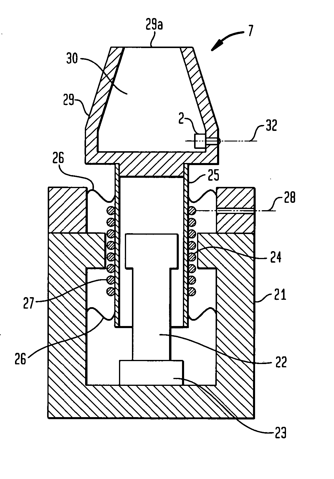
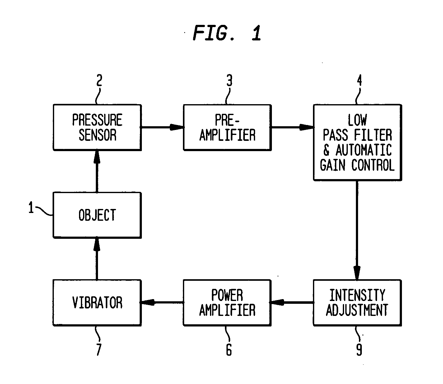
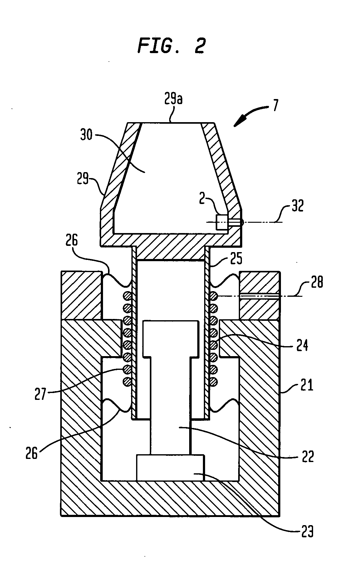
[0017] The massager according to the invention is built upon the self-excited, positive-feedback, mechanical-impedance-matched vibration control system diagrammed in FIG. 1. Indicated at 1 in this diagram is the object of massaging which usually is some part of the human body. A pressure sensor 2 is installed at or adjacent a hollow, open-ended contact piece, not shown in FIG. 1, of the massager which is to be held against the object 1. In practice the pressure sensor 2 may take the form of any such known devices as the omnidirectional microphone, piezoelectric converter, or semiconductor device capable of translating pneumatic pressure variations into an electric signal. Chosen from among any such conventional contrivances, the pressure sensor 2 is herein used to sense variations in the pneumatic pressure of the cavity defined by the contact piece as the latter is held against the object 1, as will be subsequently detailed with reference to FIG. 2.

[0018] The pressure sensor 2 has ...


PUM


Abstract

A hand-held massager capable of self-excited, impedance-matched vibration for optimal massaging of each particular body part of each particular individual. The massager includes a hollow, open-ended contact piece to which is coupled a vibrator and which is to be held against a desired body part. A pressure sensor is mounted to the contact piece for sensing pressure variations in the cavity in the contact piece while the open end thereof is held against the body part, in order to ascertain the mechanical impedance of that body part. A closed-loop, electropneumatic vibration control system makes it possible for the mechanical impedance to be fed back to the vibrator, causing the latter to make self-induced vibration. Thus the desired body part is optimally massaged at its resonance frequency.

Description

BACKGROUND OF THE INVENTION [0001] This invention relates to massagers in general and, in particular, to those of self-excited vibration variety. More particularly, the invention pertains to a hand-held massager featuring a closed-loop electropneumatic vibration control system for positive feedback of the mechanical impedance of the object of massaging (usually, some body part) to a vibrator. This vibrator is therefore self-excited to vibrate at a resonance frequency of the object and hence to massage the same at the frequency optimal to that particular object. [0002] Vibrating massagers, having a mechanically vibrating part or parts to be held against desired body parts, are well-known. In designing a massager, one can ascertain the resonance frequency of the mechanical impedance of a particular body part, and massage the object at that frequency. See Japanese Unexamined Patent Publication No. 58-138455, which discusses attaching both acceleration and pressure sensors to the part t...

Claims


Application Information

Patent Timeline
IPC IPC(8): A61H23/02A61H1/00A61H9/00A61H23/04
CPCA61H9/0007A61H2230/00A61H2201/5007A61H9/005
Inventor TAKASHIMA, MITSURU
Owner M I LABIRIES
Why Eureka
Try Eureka